
Product Description
Types of gas springs
1. Support gas spring
Also called free-type gas spring. Support rod. It is the most widely used gas spring. It mainly plays a supporting role, with only the shortest and longest positions, and cannot stop by itself during the stroke. It is most widely used in mechanical equipment, furniture and other fields.
2. Lockable(Controllable) gas spring
The controllable gas spring can be locked at any position of the entire stroke, mainly through the controller (handle or cable) to achieve the effect, but also through the expansion and contraction of the piston rod. When the controller is adjusted to stop at the desired position, the valve will be closed and the live cooling rod will be locked in the required position. When locking occurs, locking can be achieved. However, if the locking force is exceeded, the locking function will no longer be effective.
3. Damper
Damper features reduce inertia and reduce speed by changing size. Its resistance changes with the speed of operation. The speed of the connected mechanism can be significantly damped.
4. Tensile gas spring
Also known as a traction gas spring, it uses an internal piston rod to achieve basic positioning. It is a special gas spring. The supporting gas spring is in the longest position when it is in a free state. After receiving external force, it moves from the longest position to the shortest position, while the free state of the traction gas spring is at The shortest position, running from the shortest to the longest when being pulled. Traction gas springs also have corresponding free type, self-locking type and so on.
YQ series air bombs are widely used in automobile, household, computer, fitness equipment, textile, printing, food, tobacco, woodworking and other machinery, and can play the role of lifting, suspending, closing and so on.
The product structure is reasonable, and the installation and maintenance are convenient. No external power is needed when working, saving energy. The lifting force is basically constant throughout the working stroke, and the end of the stroke has a buffer mechanism to avoid damage to components. The lifting member can be stopped in any position.
| MODEL | d(mm) | D(mm) | L(mm) | S(mm) | Force(kgf) |
| YQ13 | Φ6 | Φ15 | 100-550 | 50-200 | 5-35 |
| YQ16 | Φ8 | Φ18 | 210-580 | 50-220 | 15-50 |
| YQ20A | Φ10 | Φ22 | 300-700 | 100-300 | 30-80 |
| YQ20B | Φ12 | Φ22 | 400-700 | 100-300 | 40-100 |
| YQ25A | Φ12 | Φ27 | 600-800 | 220-350 | 60-130 |
| YQ25B | Φ14 | Φ28 | 600-900 | 220-350 | 100-300 |
| YQ25C | Φ16 | Φ28 | 600-1200 | 220-900 | 100-300 |
sample.the length, stroke,pressure can be customized
Gas spring installation location selection
There are 2 optional installation styles:
1. AO is less than the length of OB
2. OB is less than the length of AO
• Calculate the approximate stroke of the gas spring used when setting points A and B first:
The AB length after opening the lid minus the AB length after closing is equal to the required air bomb stroke;
Re-calculate whether the selected gas bomb praise is reasonable:
Gas spring stroke x2+80mm=AB length after opening.
Note: If the result obtained is greater than the length of AB, then it is necessary to move point A to point 0 or point B to move to point O to increase the length of point AB, that is, increase the length of the gas spring.
YK series gas springs are suitable for various occasions where the angle and height need t be adjusted. The piston rod can be stopped at any position under human manipulation. YK series gas springs operate flexibly, work stably and reliably. Can be designed and manufactured according to user requirements. For matters needing attention, please refer to the YQ series gas spring.
| MODEL | D(mm) | d1(mm) | L(mm) | S(mm) | Thread diameter | Force(kgf) |
| Lockable YK | Φ22 | Φ10 | 225 | 60 | M10*1 | 300-700 |
| 210 | 50 | |||||
| 200 | 40 | |||||
| 130 | 30 | |||||
| Φ28 | 760 | 280 | 300-900 | |||
| 175 | 50 | |||||
| 170 | 42 | |||||
| 155 | 40 | |||||
| 128 | 28 |
This product is divided into pure oil, pure gas, oil and gas mixing, oil and gas separation and other construction machinery shock absorbers. This product is widely used in the shock absorption of engineering vehicle seats, which can effectively eliminate the vibration caused by the mechanical spring under the action of gravity. The aftershocks make the driver and passengers feel smooth and comfortable.
The oil-gas hybrid shock absorber has a good gas buffering effect and is the first choice shock absorber for modern engineering vehicle seats.
1. Samples can be offered to test before placing orders.
2. Low MOQ. Small orders are accepted.
3. OEM & ODM. Customization service is offered, including logo, laser marking.
4. Outstanding R&D ability,including product development and mould development.
5. Great pre-sales and after sales service.
HangZhou Manjia Youchuang Household Products Co., Ltd. is a professional dampers and gas springs manufacturer which collects research, design, production and sale.
Our technical backbone has been engaged in the R&D and production of dampers for more than 22 years experience. The professional and well trained production department and QC staff could assure the perfect performance of our Dampers products. For the quality assurance rate of over 99.98%, and the stability of delivery time rate more than 99.96%.
Q1. Can I have a sample for testing?
A: Yes, samples are in stock, we will return sample fee back to you once you make a bulk order from us.
Q2. What about the lead time?
A: Sample needs 1-3 days, mass production time needs around 15 days for order quantity more than 10,000 pieces.
Q3. What is your MOQ?
A: Under normal circumstances, the order quantity is 1000 pieces. If you need less than 1,000 pieces, please contact customer service.
Q4. How do you ship the goods and how long does it take to arrive?
A: We usually ship by DHL, UPS, FedEx or TNT. It usually takes 3-5 days to arrive. Shipping time depend on the shipping way you choose.
Q5. Can I print my logo on the product?
A: Yes. Please inform us formally before our production and confirm the design firstly based on our sample. Customized design is available. OEM and ODM are offered.
Q6. Do you offer guarantee for the products?
A: Yes, we offer 1 year warranty to our products.
Q7: How to deal with the faulty?
A: Our products are produced in strict quality control system and the defective rate will be less than 0.2%.During the guarantee period, we will send new dampers with new order for small quantity. For defective batch products, we will repair them and resend them to you or we can discuss the solution.
/* March 10, 2571 17:59:20 */!function(){function s(e,r){var a,o={};try{e&&e.split(“,”).forEach(function(e,t){e&&(a=e.match(/(.*?):(.*)$/))&&1
| Function: | Pressed, Phonation, Buffer, Drive, Restoration, Measurement |
|---|---|
| Material: | Alloy |
| Load Type: | Compression |
| Samples: |
US$ 15/Piece
1 Piece(Min.Order) | Order Sample |
|---|
| Customization: |
Available
|
|
|---|
.shipping-cost-tm .tm-status-off{background: none;padding:0;color: #1470cc}
|
Shipping Cost:
Estimated freight per unit. |
about shipping cost and estimated delivery time. |
|---|
| Payment Method: |
|
|---|---|
|
Initial Payment Full Payment |
| Currency: | US$ |
|---|
| Return&refunds: | You can apply for a refund up to 30 days after receipt of the products. |
|---|
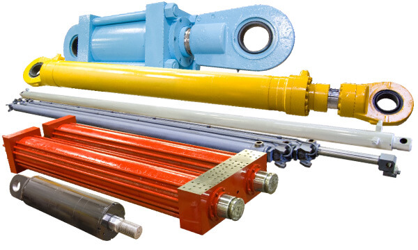
Can lift cylinders be used in hydraulic vehicle lifts?
Yes, lift cylinders are commonly used in hydraulic vehicle lifts. Here’s an explanation of their utilization in hydraulic vehicle lifts:
Hydraulic vehicle lifts are devices used to raise vehicles for maintenance, repairs, or storage purposes. Lift cylinders play a crucial role in the lifting operation of these hydraulic lifts.
In hydraulic vehicle lifts, lift cylinders are typically positioned vertically and connected to the lifting platform or arms. The lift cylinders work by converting hydraulic pressure into mechanical force, allowing the platform or arms to lift the vehicle. When the hydraulic system is activated, the hydraulic fluid is pressurized, and it flows into the lift cylinders. The force exerted by the pressurized fluid causes the lift cylinders to extend, resulting in the upward movement of the lifting platform or arms.
Lift cylinders used in hydraulic vehicle lifts are usually hydraulic cylinders. Hydraulic systems offer the advantages of smooth operation, precise control, and high lifting capacities. The hydraulic system includes a pump, control valves, hydraulic lines, and the lift cylinders. By controlling the flow of hydraulic fluid to the lift cylinders, operators can easily adjust the lifting height and position of the vehicle.
One of the key benefits of using lift cylinders in hydraulic vehicle lifts is their ability to provide stable and controlled lifting. The lift cylinders are designed to handle the weight of vehicles and ensure safe and secure lifting. They offer reliable support and stability throughout the lifting process, allowing technicians to work on vehicles with confidence.
In addition to lifting capabilities, lift cylinders in hydraulic vehicle lifts may incorporate safety features such as locking mechanisms or overload protection. These safety measures enhance the overall performance and reliability of the lifts, ensuring the safety of both the vehicle and the operators.
Overall, lift cylinders are integral components in hydraulic vehicle lifts, enabling the vertical lifting motion and providing stability during vehicle maintenance and repair operations. Their hydraulic operation, strength, and safety features make them essential for efficient and safe vehicle lifting.
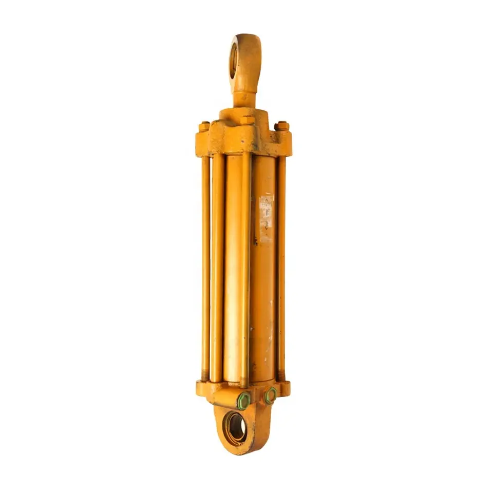
How Does a Lift Cylinder Contribute to Precise Load Handling and Positioning?
A lift cylinder plays a crucial role in achieving precise load handling and positioning in various applications. It is a hydraulic component commonly used in material handling equipment, including forklifts, cranes, and other lifting devices. The lift cylinder utilizes hydraulic power to control the vertical movement of loads, allowing for precise and controlled lifting, lowering, and positioning. Here’s a detailed explanation of how a lift cylinder contributes to precise load handling and positioning:
- Vertical Lifting:
- Load Stability:
- Positioning Control:
- Load Balancing:
- Controlled Speed and Acceleration:
- Force Feedback and Sensing:
The primary function of a lift cylinder is to provide the vertical lifting force required to raise and lower loads. When hydraulic pressure is applied to the cylinder, it extends or retracts the piston rod, depending on the design. This controlled extension or retraction enables the lift cylinder to raise or lower the load with precision. The hydraulic system allows operators to adjust the lifting speed and control the movement of the cylinder, ensuring smooth and accurate load handling.
One of the key factors in precise load handling is maintaining load stability throughout the lifting and positioning process. Lift cylinders are designed to provide a stable lifting platform by minimizing unwanted movements or vibrations. The hydraulic system, combined with the mechanical structure of the cylinder, offers excellent control over the load’s vertical movement, preventing sudden shifts or instability. This stability allows operators to handle delicate or fragile loads without compromising their integrity.
A lift cylinder offers precise positioning control, enabling operators to place the load accurately at the desired location. By regulating the hydraulic pressure, operators can control the speed and direction of the cylinder’s movement. This control allows for fine adjustments during the lifting or lowering process, ensuring that the load is positioned precisely according to the requirements. The hydraulic system offers responsiveness and sensitivity, allowing for real-time adjustments for optimal load placement.
Load balancing is essential for maintaining stability and preventing excessive stress on the lifting equipment. Lift cylinders are often used in combination with other hydraulic components, such as counterbalance valves or load sensing systems, to achieve load balancing. These systems monitor the load and adjust the hydraulic pressure within the lift cylinder to ensure that the load remains balanced during lifting and lowering operations. By maintaining load balance, the lift cylinder contributes to precise load handling and positioning, reducing the risk of accidents or damage.
Precise load handling requires controlled speed and acceleration during lifting and lowering operations. Lift cylinders, integrated with hydraulic control valves, allow for precise adjustment of the lifting speed and acceleration profile. Operators can control the flow rate of hydraulic fluid entering or exiting the cylinder, regulating the speed of the piston’s movement. This control over speed and acceleration enables smooth and gradual load handling, preventing sudden jolts or jerky movements that could affect load positioning accuracy.
Some advanced lift cylinder systems incorporate force feedback mechanisms or load sensing capabilities. These features provide operators with real-time information on the load’s weight or force exerted on the cylinder. By receiving feedback on the load conditions, operators can make precise adjustments to the lifting or lowering operation. This feedback mechanism enhances load handling precision, allowing operators to adapt to changing load characteristics and ensure accurate positioning.
A lift cylinder’s ability to provide vertical lifting force, maintain load stability, offer precise positioning control, assist in load balancing, enable controlled speed and acceleration, and incorporate force feedback or load sensing capabilities all contribute to precise load handling and positioning. These features make lift cylinders valuable components in material handling equipment, ensuring safe and efficient handling of loads in various industries and applications.
What is a lift cylinder and how does it function in hydraulic systems?
A lift cylinder, also known as a hydraulic lift cylinder or hydraulic lifting cylinder, is a device used in hydraulic systems to generate linear motion and provide lifting force. It is a type of hydraulic actuator that converts hydraulic pressure into mechanical force to lift heavy loads. Here’s an explanation of what a lift cylinder is and how it functions in hydraulic systems:
A lift cylinder consists of a cylindrical barrel, a piston, and a rod. The barrel is a hollow tube that houses the piston and allows fluid to flow in and out. The piston is a cylindrical component that separates the barrel into two chambers. The rod, attached to the piston, extends from the cylinder to connect with the load or the mechanism being lifted.
The lift cylinder operates based on the principles of Pascal’s law, which states that pressure exerted on a fluid in a confined space is transmitted equally in all directions. Here’s how a lift cylinder functions:
1. Extension:
When pressurized hydraulic fluid enters one side of the cylinder (the chamber behind the piston), it applies force on the piston, causing it to move in the direction of the load. This movement extends the rod outward, lifting or pushing the load.
2. Retraction:
Conversely, when the hydraulic fluid is supplied to the other side of the cylinder (the chamber in front of the piston), the pressure differential causes the piston to move in the opposite direction. This retracts the rod, lowering or pulling the load.
3. Control Valve:
The flow of hydraulic fluid into and out of the lift cylinder is controlled by a directional control valve. The valve regulates the direction and amount of fluid entering the cylinder, determining whether the cylinder extends or retracts. This control allows for precise and controlled lifting and lowering of the load.
4. Force and Load Capacity:
The force generated by the lift cylinder is determined by the hydraulic pressure applied to the piston and the effective area of the piston. By increasing or decreasing the hydraulic pressure, the lifting force can be adjusted to meet the specific load requirements.
5. Application:
Lift cylinders are widely used in various hydraulic systems, including hydraulic lifts, cranes, forklifts, dump trucks, and construction equipment. They provide the necessary force to lift heavy objects, perform material handling tasks, and support heavy loads in a controlled and efficient manner.
In summary, a lift cylinder is a hydraulic actuator that converts hydraulic pressure into mechanical force for lifting heavy loads. It functions by utilizing hydraulic fluid pressure to move the piston and extend or retract the rod, enabling the lifting or lowering of the load. The control valve regulates the fluid flow, and the force generated by the lift cylinder is determined by the hydraulic pressure and piston area. Lift cylinders find extensive applications in hydraulic systems across various industries.


editor by CX 2024-02-05














