
Heavy Construction Equipment Series · Monograph VIII
Advanced Engineering of
Wheel Loader Lift Cylinders:
Mastering Breakout Force and Structural Durability
Front-end wheel loaders operate at the physical threshold of fluid power capacity, converting engine power into massive hydraulic pressure to pry consolidated rock, ore, and aggregate from earth faces. This technical guide explores the mechanical design of double-acting, welded loader lift cylinders. We analyze Z-bar linkage dynamics, 42CrMo alloy steel metallurgy, plasma-sprayed ceramic surface finishes, and structural guiding configurations designed to eliminate rod bending under extreme eccentric loads.
Ceramic Coating
Buckling Mechanics
Engineering Specifications Matrix for Loader Lift Cylinders
The following engineering specifications outline the structural, metallurgical, and operational benchmarks required for high-capacity double-acting lift cylinders deployed in earthmoving wheel loaders.
| Engineering Parameter | Heavy-Duty Loader Specification Standard |
|---|---|
| Equipment Application | Earthmoving Machinery / Front-End Wheel Loader |
| Subsystem Motion Profile | Main Boom Lifting Circuit / Double-Acting Linear Motion |
| Actuator Component Name | Boom Lift Cylinder Assembly |
| Structural Construction | Heavy-Wall Welded Architecture (DOM Tubing) |
| Piston Rod Metallurgy | 42CrMo Alloy Steel (Quenched & Tempered + Induction Hardened) |
| Rod Surface Protection | HVOF Thermal-Sprayed Ceramic / WC-CoCr Layer (>1200 HV) |
| Operating Environment Class | Severe Dynamic Shock Loads + Airborne Silica Quartz Dust |
| Primary Failure Mitigated | Column Buckling / Permanent Rod Bending under Side Loads |
| Guiding System Upgrade | Elongated Gland Housing + Centrifugal Bronze Liners + Stop Tube |
| Rated Working Pressure | 31.5 MPa to 35.0 MPa (315 – 350 Bar) Continuous |
Loader Kinematics and Lift Cylinder Mechanics
The front-end wheel loader is an essential piece of mobile equipment across quarrying, surface mining, civil infrastructure, and bulk materials handling. Its performance relies on the front linkage assembly, which must translate hydraulic power into clean bucket motion. The system uses a pair of double-acting hydraulic lift cylinders (boom cylinders) working alongside single or dual tilt cylinders to move the main boom and bucket assembly.
Most heavy-duty production loaders use Z-bar linkage geometry. This design delivers mechanical advantage during the crowd and breakout phases. As the loader approaches a material bank, the bucket edge is driven into the pile. Breakout force is generated by curling the bucket upward while simultaneously extending the lift cylinders. During this maneuver, the lift cylinders must support the combined weight of the structural boom arms, the bucket, and payloads that frequently exceed 15 metric tons, while overcoming the mechanical resistance of compacted rock.

Mechanics of the Breakout Phase
During the initial digging sequence, the lift cylinder operates at peak pressure with its rod partially extended. As hydraulic fluid enters the cap-end port, it acts upon the full surface area of the main piston, generating the force needed to raise the heavy boom assembly. The force output produced by the cylinder is expressed as:
Where Pcap represents the hydraulic system operating pressure (often between 31.5 and 35 MPa), Dbore is the cylinder inner bore diameter, Ffriction is the mechanical drag of the seal package and guide rings, and Fbackpressure is the fluid resistance inside the retracting rod-end chamber. Operating at these pressure levels means bore diameters ranging from 140 mm to over 220 mm are standard for 20-to-50-ton class loaders.
Hydrostatic Force Distribution and Pressure Spikes
When the bucket breaks through the top of a rock pile, the resistance drops suddenly. This rapid unload can create momentary fluid cavitation on the cap-end side if the pump supply cannot match the expanding chamber volume. Conversely, driving over uneven quarry terrain with a fully loaded bucket causes severe pressure spikes due to payload bounce. These dynamic shocks can exceed nominal relief valve settings, subjecting the cylinder barrel, rod eye, and mounting pins to peak stress concentrations.
Structural Dynamics of Rod Bending and Buckling
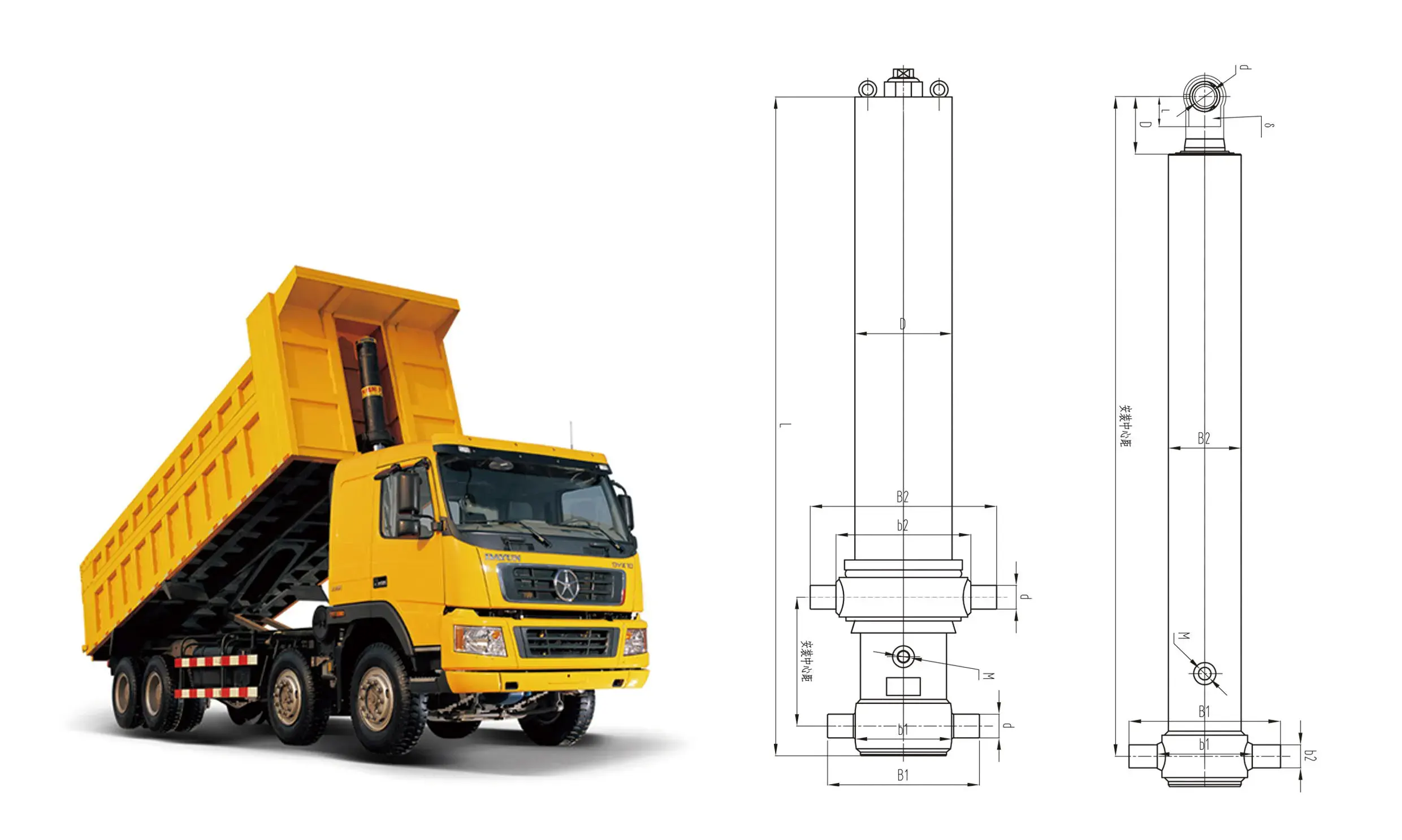
In field operations, loader lift cylinders rarely fail from simple hoop stress overpressure inside the barrel. The predominant structural failure mode is permanent plastic deformation or elastic instability of the piston rod—commonly referred to as rod bending or column buckling.
An extended loader lift cylinder behaves as a long, slender column subjected to compressive loads. The classical critical buckling load Pcr is evaluated using Euler’s column formulation, modified by empirical safety factors for mobile equipment pins:
In this equation, E represents the elastic modulus of the rod steel (210 GPa for low-alloy structural steels), I = π × drod4 / 64 is the area moment of inertia for a solid circular rod of diameter drod, Lext is the fully extended length between pin centers, and K is the column fixity factor dictated by the spherical plain bearings used in the clevis mounts.
Asymmetrical Loading and Lateral Shear Stress
Pure axial compression rarely occurs in real-world quarrying. If a wheel loader operator strikes an embedded boulder with only the corner edge of the bucket, an asymmetrical force distribution flows through the front structure. This off-center impact creates a twisting moment on the boom assembly, introducing severe side loads (lateral shear forces) directly to the extended piston rod.
When an eccentric load acts at a distance e from the cylinder axis, the combined stress σmax within the outer fibers of the piston rod is magnified:
Where Arod is the rod cross-sectional area. The secondary bending stress term often exceeds the primary compressive stress. If σmax exceeds the yield strength (σy) of the rod steel, permanent micro-bending occurs.
Micro-Deflection and Seal Destructive Cascades
Even minor rod deflections disrupt the concentricity between the rod, gland, and cylinder barrel. As the bent rod retracts through the head gland, it concentrates load onto one side of the internal guide bushes. This localized force compresses the wear bands beyond their elastic limit, resulting in metal-to-metal contact between the steel rod and the gland housing. The resulting metal scoring cuts into the primary polyurethane seals and wiper elements, causing external hydraulic oil leaks and internal pressure bypass.
Advanced Guiding Architectures to Mitigate Lateral Forces
Preventing structural rod failure requires engineering modifications within the cylinder gland and piston support interfaces. Heavy-duty loader lift cylinders utilize an enhanced guiding package engineered to distribute lateral shear stresses over a wider surface area.
Optimizing the Bearing Overlap Ratio
The bearing overlap distance—the axial gap between the piston wear rings and the gland guide bushes at full stroke extension—is a crucial design variable. Standard industrial cylinders often use an overlap ratio (Loverlap / Dbore) of 0.8 to 1.0 to save material cost. For wheel loader applications, this ratio is increased to 1.5–2.0.
Extending the physical length of the gland housing increases the guide distance, reducing the unit bearing reaction force Fbearing caused by side loads Fside according to the static moment balance:
A longer Loverlap reduces peak pressure on the guide rings, keeping stress levels safely below the material’s yield point under peak bending moments.
High-Compressive Strength Wear Ring Tribology
Material selection for guide bands is critical under high load conditions. Traditional glass-filled nylon or standard PTFE wear rings can deform under heavy impact loads. Modern loader lift cylinders utilize bronze-filled PTFE composite rings, centrifugally cast high-tensile manganese bronze bushes, or woven fabric reinforced resin matrices impregnated with solid lubricants (such as MoS2 and graphite).
Centrifugally Cast Bronze Liners
High-leaded bronze or aluminum bronze sleeves inserted into the gland body offer compressive yield strengths exceeding 280 MPa. They handle localized side-load spikes without permanent distortion, while their soft metallic matrix embeds microscopic wear particles to protect the hard rod surface.
Internal Stop Tube Integration
In long-stroke cylinders, a steel spacer ring (stop tube) is placed over the rod between the piston and the gland. This spacer acts as a mechanical stop, preventing the piston from travelling to the absolute end of the barrel. It ensures a minimum guide overlap is maintained at full extension, improving column stability.
Metallurgical Engineering: The Advantages of 42CrMo Steel Alloy
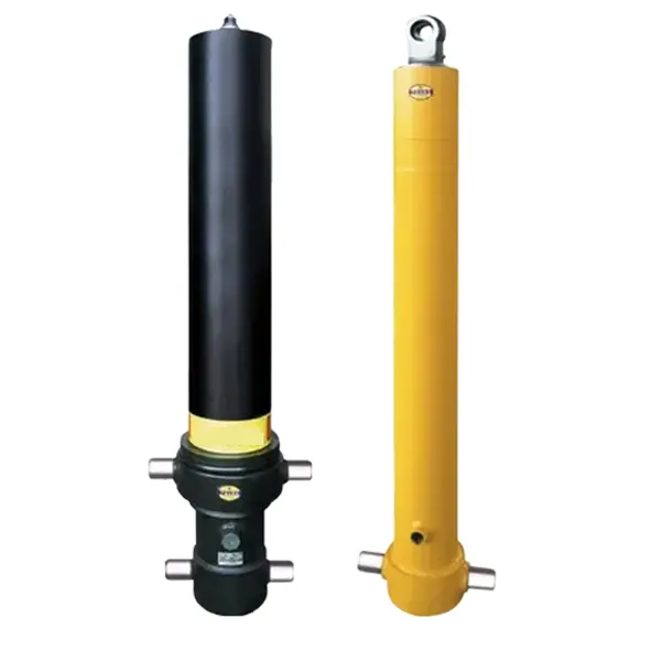
While optimizing bearing geometry helps distribute side loads, the ultimate bending resistance of the piston rod depends on the mechanical properties of its core steel. Standard industrial cylinders often use medium carbon steels like AISI 1045 or ST52-3, which have yield strengths around 350–450 MPa. These materials are susceptible to permanent bending under the severe shock loads encountered in quarry operations.
Heavy-duty mobile equipment applications require higher-grade materials, such as 42CrMo alloy steel (equivalent to AISI 4140 / 42CrMo4 / 708M40). This chromium-molybdenum low-alloy steel delivers an optimal balance of tensile strength, fatigue endurance, and impact toughness.
Chemical Composition and Hardenability Mechanics
The chemical composition of 42CrMo steel is balanced to maximize hardenability across large cross-sections, ensuring consistent mechanical properties from the outer surface to the core of heavy-diameter rods:
- ▸
Carbon (C: 0.38 – 0.45%): Provides the necessary carbon content to achieve high strength and hardness following thermal treatment. - ▸
Chromium (Cr: 0.90 – 1.20%): Increases deep hardenability, elevates tensile strength, and improves resistance to surface abrasion. - ▸
Molybdenum (Mo: 0.15 – 0.30%): Refines grain structure, mitigates temper brittleness, and enhances high-temperature strength during heavy duty cycles.
Thermal Processing: Quenching, Tempering, and Case Depth
Raw 42CrMo bar stock undergoes a two-stage thermal treatment process to develop its full mechanical potential. First, the material is subject to full Quenching and Tempering (Q&T). The steel is heated to its austenitizing temperature (850°C – 880°C), quenched in polymer or oil to produce a fully martensitic structure, and then tempered at 560°C – 620°C. This heat treatment raises the core yield strength (σ0.2) above 850 MPa and ultimate tensile strength (σb) above 1000 MPa, with Charpy V-notch impact toughness exceeding 45 J at -20°C.
Following Q&T processing, the rod surface undergoes medium-frequency induction hardening. This process rapidly heats the outer layer to 900°C before immediate water spray quenching. This creates an outer hardened case (55 to 60 HRC) to a controlled depth of 2.5 to 4.5 mm. The hard outer case resists surface indentation from rock impacts, while the tough Q&T core absorbs dynamic shock loads without catastrophic brittle fracture.
Surface Engineering: Ceramic Coatings vs. Traditional Hard Chrome
A 42CrMo heat-treated core provides the mechanical strength needed to resist bending, but the rod’s outer surface must withstand harsh environmental conditions. Loader lift cylinders operate in environments filled with airborne quartz dust (silica hardness ~1100 HV) and subject to flying gravel impact.
The Degradation Mechanics of Hard Chrome Plating
Electroplated hard chrome has traditionally served as the standard surface coating for hydraulic rods. However, it presents inherent limitations in severe mining environments. Microscopic cracking is an unavoidable byproduct of electrodeposition, forming pathways through which moisture, salts, and airborne contaminants can reach the underlying steel substrate.
When stone impacts strike a chrome-plated rod, the brittle coating can chip or fracture away from the substrate. Corrosion then develops beneath the chrome, forming iron oxide scale that lifts the surrounding plating. The resulting rough edges damage the primary gland seals as the rod retracts, leading to oil leaks.
HVOF Ceramic Coating Application and Tribological Performance
To address these vulnerabilities, premium loader cylinders increasingly utilize thermal-sprayed ceramic and carbide coatings, applied via High-Velocity Oxygen Fuel (HVOF) or plasma arc deposition systems. Common coating formulations include Chromium Oxide (Cr2O3), Alumina-Titania (Al2O3/TiO2), and Tungsten Carbide-Cobalt Chrome (WC-CoCr).
Key Advantages of HVOF Ceramic Surface Technology
- Superior Surface Hardness: HVOF ceramic layers achieve hardness ratings between 1200 HV0.3 and 1400 HV0.3—substantially harder than silica quartz dust. This eliminates abrasive fine-particle scratching.
- Dense Non-Porous Structure: Thermal spray deposition accelerates particles to supersonic velocities (>1000 m/s), creating dense coatings with porosity levels below 0.5%. This provides a barrier against moisture and corrosive slurry.
- High Mechanical Bond Strength: The mechanical keying and micro-welding action produces bond strengths exceeding 70 MPa, resisting delamination when subjected to stone impacts in the field.
Welded Cylinder Architecture and High-Pressure Sealing Systems

Heavy mobile machinery requires compact, structurally rigid hydraulic actuators. Tie-rod cylinder designs are ill-suited for construction loaders due to their bulky footprint, weight penalty, and susceptibility to tie-rod stretch under high shock pressures. Wheel loader lift cylinders are constructed using fully welded heavy-duty architectures.
Full-Penetration Robotic Weld Integrity
The cylinder barrel is produced from seamless, heavy-walled steel tubing (such as E355 or 27SiMn), precision skived and roller-burnished to achieve an internal surface finish of Ra < 0.2 μm. The bottom clevis base and front gland flange are attached using multi-pass robotic Metal Active Gas (MAG) welding under strict pre-heat and post-weld controlled cooling protocols.
Structural welds must achieve 100% full-penetration joint profiles verified through Non-Destructive Testing (NDT). Ultrasonic Testing (UT) inspects the weld volume for subsurface inclusions or lack of fusion, while Magnetic Particle Inspection (MPI) confirms the absence of surface cracks around critical mounting pin bosses.
Multi-Stage Sealing Strategy for Contaminated Environments
Reliable sealing under high pressure and dirty conditions requires a coordinated multi-stage seal configuration inside the gland housing:
- 1.
Heavy-Duty Metal-Cased Scraper / Wiper Seal: Positioned at the outer gland face. It features an aggressive Polyurethane scraper lip reinforced with a steel cage to remove dried mud, ice, and packed quarry dust from the extending rod. - 2.
Buffer Seal Ring with Integrated Pressure Relief: Located upstream of the main rod seal. It absorbs high system pressure spikes, venting trapped fluid back to the main system if pressure between seals rises too high. - 3.
Primary Polyurethane U-Cup Rod Seal: Featuring elastomer energizers that maintain positive sealing force even during low-temperature morning startups and low-pressure lowering cycles.
Specifying a robust heavy-duty lift cylinder engineered with these multi-stage gland seals helps prevent fluid contamination and unplanned maintenance downtime.
Preventive Maintenance, Fluid Hygiene, and Diagnostic Protocols
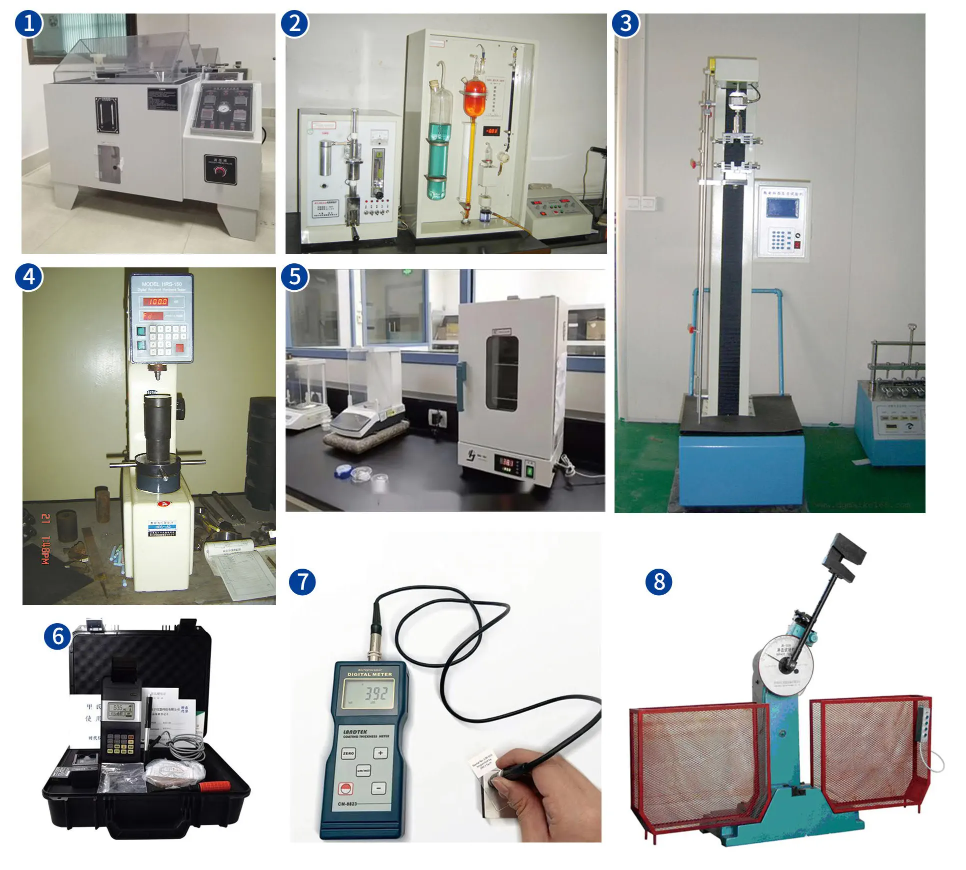
Even with 42CrMo steel rods, ceramic surface finishes, and reinforced guide glands, a lift cylinder’s working lifespan depends heavily on proper hydraulic fluid maintenance. A loader’s hydraulic system breathes in air during normal operations. As the large-displacement lift cylinders extend, fluid levels in the main reservoir drop, drawing ambient air—and fine airborne dust—into the tank through the breather assembly.
ISO Cleanliness and Filtration Management
Fine silica particles under 10 microns can slip past standard reservoir breathers if filters are neglected. Once suspended in hydraulic oil, this particulate matter acts as a grinding compound under high pressure, wearing down internal valve spools and piston seal lips. Maintaining fluid cleanliness to ISO 4406 code 18/16/13 or cleaner is essential for maximizing component life.
Systematic Hydraulic Drift Troubleshooting
When a loader boom drifts downward with the control valves in neutral, technicians must isolate whether the issue stems from the cylinder seals or the main control valve spool:
Step 1: Mechanical Isolation Test
Raise the empty loader boom to half height, stop the engine, and support the boom safely with mechanical maintenance stands. Disconnect the return line at the cylinder rod end and cap the hose. Remove the mechanical stands. If oil drips continuously from the open rod-end port as the boom lowers under its own weight, fluid is bypassing the internal piston seals.
Step 2: Control Valve Spool Verification
If no oil escapes from the cylinder port during the isolation test yet the boom still drifts downward when reconnecting the lines, the fluid leak is occurring across the worn spool land inside the main directional control valve block or through a weeping circuit relief valve.
Strategic Sourcing and Total Cost of Ownership
For fleet managers running high-production equipment, unplanned machine downtime carries significant costs. Selecting lower-cost replacement cylinders built with standard carbon steel rods or plain chrome plating often proves expensive over time due to frequent teardowns, seal replacements, and lost operating hours.
Procurement teams managing mobile equipment fleets can evaluate technical offerings across leading specialized mobile machinery hydraulic cylinder sources to review engineering specifications, seal configurations, and material options. Equipping machines with front top lifting cylinders engineered with 42CrMo alloy steel rods, ceramic finishes, and extended guide glands helps ensure long-term durability and lower total operating costs in demanding working environments.
Optimize Your Machine’s Breakout Power
Prevent structural rod bending, protect against silica abrasive wear, and maintain reliable boom lifting power. Explore our engineered line of heavy-duty, ceramic-coated wheel loader lift cylinders designed for high-load construction environments.














