TECHNICAL GUIDE · ACCUMULATOR CIRCUITS · HYDRAULIC LIFT CYLINDERS

Hydraulic Accumulator
and Lift Cylinder Circuits
Energy Storage · Fast Response · Ride Control

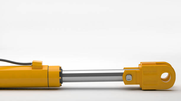
A hydraulic accumulator paired with a lift cylinder unlocks capabilities that a pump-only system cannot provide: instantaneous peak flow several times the pump’s rated output, pressure-maintained load holding without a running pump, shock absorption in mobile equipment suspension cylinders, and controlled emergency lowering when primary power fails. The combination of accumulator and lift cylinder is found in applications from offshore platform stabilisation to automated press loading to AWP ride control — wherever the pump cannot respond quickly enough or must not run continuously. This guide covers the principal accumulator-lift cylinder circuit configurations, sizing methods, and safety requirements.

Energy Storage
Fast Response
Ride Control

LIFT CYLINDERS · ACCUMULATOR CIRCUIT ENGINEERING · JULY 2026


REFERENCE · ACCUMULATOR-LIFT CYLINDER CIRCUIT KEY PARAMETERS

PEAK FLOW BOOST

3–10× pump

An accumulator can discharge at 3–10× the pump’s rated flow during short-duration lift cylinder demand peaks

PRE-CHARGE RATIO

0.6–0.9 × P1

Nitrogen pre-charge pressure set at 60–90% of minimum lift cylinder working pressure — the standard starting point for sizing

SAFETY REGULATION

PED 2014/68/EU

Pressure Equipment Directive — all accumulators above 0.5 bar·litre must meet PED classification and carry CE marking in the EU

INSPECTION INTERVAL

Every 2 years

Most jurisdictions require formal inspection of accumulators above the PED threshold every 2 years — pre-charge and bladder condition checked

섹션 01

Accumulator Types and Operating Principles

Hydraulic accumulator paired with lift cylinder circuit energy storage fast response emergency lowering
Hydraulic accumulator and lift cylinder circuit — the accumulator stores energy in compressed nitrogen and releases it rapidly to the lift cylinder circuit on demand. Three accumulator types are used in lift cylinder applications: the bladder accumulator (most common — 1 to 500 litres, fast response), the piston accumulator (heavy-duty, large volume, tolerates contamination better), and the diaphragm accumulator (compact, low volume, for small lift cylinder circuits).

All hydraulic accumulators store energy by compressing a gas charge (nitrogen) through the displacement of oil. The three types differ in the separator element between gas and oil:

BLADDER ACCUMULATOR

A flexible rubber bladder separates the gas and oil charges within a pressure vessel. The most common type for lift cylinder circuits — rapid response due to the low inertia of the bladder, suitable for pulse damping, peak flow supply, and ride control. Available 1–500 litres. The bladder material must be compatible with the hydraulic oil — NBR for mineral oil, EPDM for HFA/HFC fluids. Bladder life: 3–10 years depending on duty cycle and contamination.

PISTON ACCUMULATOR

A free-floating piston with seals separates gas and oil. Better suited for large volumes (10–1 000+ litres), high flow rates, and contaminated oil environments where bladder extrusion through the inlet valve would be a risk. Slower dynamic response than bladder type due to piston inertia. Used for emergency lowering reservoirs, large press buffer systems, and offshore platform stabilisation lift cylinder circuits.

DIAPHRAGM ACCUMULATOR

A flexible membrane bonded across the vessel separates gas and oil. Compact, low volume (0.1–10 litres), very fast response, and maintenance-free — no replaceable bladder. Used for small lift cylinder circuits requiring pulse damping, leakage compensation, or very small emergency volumes. Not suitable for high flow rates or large volume demands.

섹션 02

Peak Flow and Energy Storage for Lift Cylinder Circuits

The most common reason to add an accumulator to a lift cylinder circuit is to supply a short-duration peak flow demand that exceeds the pump’s rated output — allowing a smaller, cheaper pump to be used while still achieving the required cycle time. This configuration is called a pump-accumulator circuit:

CHARGING
PHASE

Between lift cylinder demand cycles, the pump charges the accumulator from minimum pressure (P1) to maximum pressure (P2). The pump runs at its rated flow — a small pump can fully charge the accumulator in the inter-cycle interval. The stored oil volume represents the energy available for the next lift cylinder demand. For the accumulator to adequately support the lift cylinder, the inter-cycle interval must be long enough for the pump to fully recharge it before the next demand.

DEMAND
PHASE

When the lift cylinder demands flow, the accumulator discharges at a rate limited only by the valve and piping resistance — potentially 5–10× the pump’s rated output during the first seconds of discharge. The pump also supplies flow simultaneously, but the accumulator contributes the majority of the peak demand. As the accumulator pressure falls from P2 toward P1, the discharge rate decreases and the pump’s contribution increases. The lift cylinder receives a declining pressure supply as the accumulator empties.

압력
LIMITATION

The declining pressure during accumulator discharge means the lift cylinder receives less force as the stroke progresses — a critical consideration for applications where full force must be maintained throughout the stroke. If constant force is required, the accumulator pressure range P2/P1 must be set so that the minimum pressure P1 is still above the minimum pressure needed by the lift cylinder to complete its stroke under full load. A wide P2/P1 ratio gives more usable energy but a larger pressure variation; a narrow ratio gives more consistent force but less stored energy.

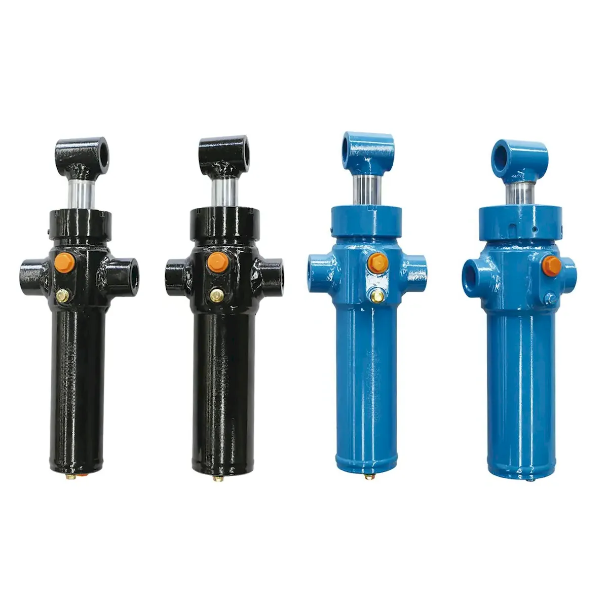
For lift cylinder circuits where an accumulator will be added to an existing pump-only system, confirm that the existing pump’s pressure relief valve is set above the accumulator maximum charge pressure P2 — otherwise the pump will open the relief valve before the accumulator reaches full charge. The 리프트 실린더 product range includes configurations with high-pressure ports suitable for direct accumulator line connection.

섹션 03

Ride Control — Mobile Equipment Suspension Lift Cylinders

Hydraulic accumulator ride control lift cylinder forwarder telehandler AWP suspension rough terrain
Ride control accumulator for mobile lift cylinder systems — when connected to the cap-end of a forwarder crane cylinder or telehandler boom cylinder during transport, the accumulator allows the cylinder to compress and extend slightly as the machine traverses rough terrain. The nitrogen in the accumulator acts as a spring absorbing the worst ground shock loads — without ride control, repeated impacts at road speed transfer directly into the boom structure and machine frame, causing cumulative fatigue damage to welded joints.

Ride control is the application of an accumulator to a mobile equipment lift cylinder — typically a boom or crane arm cylinder — to cushion the boom’s movement during road transport or rough-terrain travel at speed. Without ride control, every ground bump is transmitted directly through the rigid hydraulic oil column in the lift cylinder to the boom structure and machine frame:

CIRCUIT DESIGN

A solenoid valve connects the accumulator to the cap-end port of the boom lift cylinder during travel mode. The valve is opened by the operator or automatically at road speed above a set threshold. The boom can now move slightly — the nitrogen in the accumulator compresses as the boom bounces up (lift cylinder extends under inertia load) and expands when the boom falls back. A check valve prevents the boom from descending too far; a pressure-limiting relief valve prevents excessive boom rise.

ACCUMULATOR SIZING

The ride control accumulator must be sized so that the desired boom travel range (typically ±50–100 mm vertical) corresponds to a pressure change of 10–30% of the nominal lift cylinder operating pressure. Too small an accumulator produces a very stiff spring (small volume change for large pressure change) — the ride control has little effect. Too large an accumulator produces an excessively soft spring — the boom bounces through its full travel on every bump.

MACHINES USING RIDE CONTROL

Forwarder loader cranes, telehandler boom lift cylinders, agricultural sprayer boom suspension, and rough-terrain aerial work platform outrigger lift cylinders all commonly use ride control accumulators. The ride control function is automatically disabled when the machine changes from travel mode to work mode — allowing full hydraulic control of the lift cylinder position during lifting operations.

섹션 04

Emergency Lowering — Accumulator as Power-Failure Backup

An accumulator used for emergency lowering stores sufficient energy to lower a raised lift cylinder platform to a safe position when primary hydraulic power fails. This function is required for personnel platforms (AWPs), dock levellers, and industrial scissor lifts by EN 280 and EN 1570 where an alternative means of safe descent must exist independent of the primary power source:

CIRCUIT
REQUIREMENT

The accumulator must remain charged to the minimum required pressure at all times when the platform is elevated — even if the pump motor has been off for hours. The accumulator is connected to the lift cylinder via a solenoid valve that opens only on an emergency lowering command (manual push-button or automatic power-loss detection). The flow must be metered through a flow control valve to achieve a controlled descent speed — uncontrolled accumulator discharge to the lift cylinder return line would cause uncontrolled platform descent at an unsafe speed.

용량
REQUIRED

The accumulator must supply enough oil volume to lower the lift cylinder from its maximum height to floor level. This volume equals the cap-end area multiplied by the maximum stroke: V_cylinder = A × stroke. For a 100 mm bore lift cylinder with 1 200 mm stroke: V_cylinder = (π/4 × 0.1²) × 1.2 = 9.4 litres. The accumulator must deliver at least this oil volume while maintaining pressure above the minimum needed to open the flow control valve throughout the descent — requiring an accumulator total volume of typically 2–3× the required oil volume to allow for gas expansion and pressure maintenance.

MONITORING
REQUIREMENT

EN 280 requires a pressure switch on the emergency accumulator with a visual or audible alarm in the operator station when the accumulator pressure falls below the minimum required for a full emergency descent. This ensures the operator knows the emergency lowering function is compromised before a situation where it would be needed arises. The accumulator pressure must be checked and confirmed above the minimum on each platform inspection — a low accumulator is a safety non-conformity that requires resolution before the machine is used.

섹션 05

Accumulator Sizing Calculation — Worked Example

Hydraulic accumulator sizing calculation for lift cylinder circuit peak flow energy storage bladder
Hydraulic accumulator sizing for a lift cylinder peak flow application — the accumulator total volume must be calculated from the required usable oil volume, the pressure operating range, and the gas behaviour during charge and discharge. The polytropic gas law (PV^n = constant) governs the relationship between pressure and volume in a bladder accumulator — using n=1.4 (adiabatic) for fast discharge cycles and n=1.0 (isothermal) for slow discharge cycles.

A standard bladder accumulator sizing calculation for a lift cylinder peak flow application proceeds through five steps. The example below sizes an accumulator to supply 8 litres of oil in 3 seconds to a lift cylinder operating between 160 and 200 bar system pressure:

WORKED EXAMPLE — 8 LITRE SUPPLY, P1 = 160 bar, P2 = 200 bar, P0 = 140 bar (pre-charge)

Required usable oil volume: ΔV = 8 litres

Gas law factor (adiabatic, n = 1.4): Ratio = (P2/P1)^(1/1.4) = (200/160)^0.714 = 1.25^0.714 = 1.175

Gas volume at P1 (minimum working pressure): V_gas_P1 = ΔV / (1 − 1/Ratio) = 8 / (1 − 1/1.175) = 8 / 0.149 = 53.7 litres

Total accumulator volume from pre-charge: V_total = V_gas_P1 × (P1/P0)^(1/n) = 53.7 × (160/140)^(1/1.4) = 53.7 × 1.143^0.714 = 53.7 × 1.101 = 59.1 litres → Select 60-litre accumulator

Verification: At P2 = 200 bar, gas volume = 60 × (140/200)^(1/1.4) = 60 × 0.7^0.714 = 60 × 0.744 = 44.6 litres. Usable oil = 60 − (60 × (140/160)^0.714) = 60 − 53.7 = 6.3 litres. Adjust to 65-litre accumulator for full 8-litre margin: V_total ≈ 65 litres. SELECTED: 65-litre bladder accumulator, P0 = 140 bar, P2 = 200 bar max

For lift cylinder circuits requiring accumulator sizing support, our engineers can calculate the correct accumulator volume, pre-charge pressure, and connection specification. The 산업 공학 유압 실린더 range includes lift cylinders with high-pressure cap-end ports and accumulator connection fittings for direct accumulator integration.

섹션 06

Safety, Inspection and Regulatory Requirements

Hydraulic accumulator inspection pre-charge pressure check bladder condition lift cylinder circuit safety
Accumulator pre-charge pressure inspection — the nitrogen pre-charge must be verified annually using a dedicated accumulator charging kit connected to the gas valve with the hydraulic pressure fully released. Checking the pre-charge while the oil side is pressurised gives a false reading and may damage the gas charge gauge. A pre-charge that has dropped below the specified value means the accumulator can no longer deliver its rated usable oil volume — the lift cylinder circuit will not receive the peak flow or emergency volume for which the system was designed.

Hydraulic accumulators are classified as pressure vessels under the EU Pressure Equipment Directive (PED 2014/68/EU) and equivalent national regulations worldwide. Every accumulator-equipped lift cylinder system must comply with the applicable pressure vessel regulations for design, certification, and periodic inspection:

PED MARKING

Any accumulator with a pressure-volume product (bar × litre) above 50 must carry CE marking under PED 2014/68/EU. A 10-litre accumulator at 200 bar has a PV product of 2 000 — well above the threshold. The CE marking must be accompanied by a Declaration of Conformity and the technical file that includes the design calculation, material certificates, and test records. Accumulators without CE marking cannot be legally installed in EU member state machinery.

DISCHARGE VALVE

Every accumulator in a lift cylinder circuit must be equipped with a manual or automatic discharge (dump) valve that allows the oil side to be fully depressurised before any maintenance work on the circuit. Forgetting to discharge the accumulator before opening a circuit containing one is one of the most common causes of serious hydraulic system injuries — the accumulator stores enough energy to eject fittings and oil at lethal velocity if a port is opened under pressure.

ANNUAL CHECK

Pre-charge pressure must be verified annually using a nitrogen charging kit with the oil side fully depressurised. The pre-charge should be within ±2 bar of the specified value. A pre-charge that has dropped more than 5 bar indicates bladder or gas valve leakage — the accumulator must be removed for inspection and re-charging before the lift cylinder circuit is returned to service. Never use air or oxygen as a substitute for nitrogen — oxygen in contact with high-pressure mineral oil is an explosion hazard.

2-YEAR INSPECTION

Most EU member states and UK regulations require formal inspection of accumulators above the PED threshold by a competent person every 2 years. The inspection covers: pre-charge verification, bladder condition (oil colour and appearance in the nitrogen side of the gas valve indicates bladder failure), external vessel condition (corrosion, impact damage, coating), and port and valve condition. The inspection record must be retained with the machine’s documentation file.

기술 관련 FAQ

Accumulator Circuit Questions

질문 1

Our lift cylinder circuit accumulator needs replacing — can we fit a larger accumulator to improve peak flow performance?

Yes, a larger accumulator will improve peak flow by storing more usable oil volume — but several constraints apply before the replacement is simply fitted. First, the mounting and pipe connection on the machine may only accommodate a specific envelope size — verify the physical space available. Second, the accumulator safety valve (if fitted to the circuit) may need re-rating for the increased oil volume — a larger accumulator can discharge more oil in a failure event, increasing the potential hazard. Third, the pump and motor may need a longer re-charge time if the accumulator total volume increases significantly — check that the inter-cycle interval is still sufficient to reach full charge before the next lift cylinder demand. Fourth, the PED classification may change — a larger vessel at the same pressure may move into a higher PED category requiring a different level of conformity assessment. Confirm all four considerations before fitting a larger unit. If the constraints are satisfied, a larger accumulator is a straightforward improvement to peak flow performance without changing the lift cylinder itself.

질문 2

The accumulator on our AWP emergency lowering circuit shows oil in the gas side when we check the pre-charge — what does this indicate?

Oil in the gas side of an accumulator unambiguously indicates that the separating element (bladder or diaphragm) has failed — the oil and nitrogen are no longer separated. The accumulator is no longer functional as an energy storage device and must be removed from service immediately. For an AWP emergency lowering accumulator, this means the machine’s emergency lowering function is unavailable — the machine must not be operated with personnel elevated until the accumulator has been replaced and the emergency function verified. To replace the bladder: depressurise the oil side completely, discharge the nitrogen charge through the gas valve, disassemble the accumulator, remove and discard the failed bladder, install the new bladder (same material and size as original), reassemble, re-charge nitrogen to the specified pre-charge pressure, and verify the pre-charge before reconnecting to the circuit. Always carry a spare accumulator bladder for AWP emergency lowering systems where the machine is remote from service facilities — the inspection interval of 2 years does not guarantee the bladder will not fail between inspections, particularly in high-cycle applications.

질문 3

Our forwarder’s ride control is activated but the boom still bounces heavily over rough ground — has the accumulator failed?

Heavy bouncing with ride control active most commonly indicates that the nitrogen pre-charge pressure has risen too high relative to the lift cylinder operating pressure — the accumulator is too stiff to allow the boom to move. This happens when the pre-charge is set correctly at one load condition and the machine is then used with a significantly lighter load — a lighter boom lift cylinder load at a lower operating pressure means the accumulator’s gas spring is too stiff relative to the force trying to compress it. Check the pre-charge: if it is above 90% of the nominal lift cylinder operating pressure with the current load, the ride control will be ineffective. Reduce the pre-charge to 60–70% of the minimum lift cylinder operating pressure at the lightest typical load. A secondary cause is that the ride control solenoid valve is partially closed — verify it is fully open when ride control is engaged by checking the valve spool movement. Finally, confirm the accumulator check valve is not stuck closed, which would prevent the boom from extending during the upward bounce phase and produce an asymmetric, one-sided ride.

질문 4

Can we use the existing lift cylinder accumulator for multiple functions — peak flow supply and emergency lowering simultaneously?

Technically yes, but it requires careful sizing and circuit design to ensure both functions receive adequate energy from the shared accumulator. The primary risk of sharing is that a peak flow demand event fully or partially discharges the accumulator, leaving insufficient pressure and volume for a subsequent emergency lowering event. To share safely, the accumulator must be sized for the sum of both requirements — not the larger of the two. Additionally, the circuit must include a minimum pressure switch that prevents the peak flow function from drawing the accumulator below the minimum emergency lowering pressure: when the pressure falls to the emergency minimum, a priority valve blocks the peak flow circuit and reserves the remaining energy exclusively for emergency lowering. This priority circuit design is more complex than separate dedicated accumulators and introduces an additional single point of failure in the priority valve. For personnel-carrying platforms where the emergency lowering function is safety-critical, the preferred and most reliable approach is to use a dedicated accumulator sized exclusively for emergency lowering, charged by the main system and isolated from all other demands. Peak flow demands are then served by a separate accumulator in the lift cylinder circuit without any risk of compromising the safety function.

ACCUMULATOR LIFT CYLINDER CIRCUIT DESIGN

Need Accumulator Integration for Your Lift Cylinder Circuit?

Our engineers size the accumulator, select the pre-charge, and specify the circuit valve arrangement for peak flow, ride control, or emergency lowering applications — paired with the correct 리프트 실린더 port configuration for direct accumulator connection.

Request Accumulator Circuit Design


편집자: Cxm