
Product Description
Crane Loader Excavator Mining Lift Platform Engineering Machinery Steel Material Screw Type Piggyback Non Weleded Telescopic Hydraulic Cylinders
Product Description
Crane Loader Excavator Mining Lift Platform Engineering Machinery Steel Material Screw Type Piggyback Non Weleded Telescopic Hydraulic Cylinders : Assemble with imported seals kits of NOK, SKF, Hallite and other brands to bring the better seal slick and the stronger persistence.
Process with the advanced technology by CNC machine tools, automatic plating and painting equipments to ensure all the parts to have the lower surface roughness and the higher performance level.
Own advanced special buffer device with independent intellectual property rights which can effectively absorb the shock to protect the cylinder work smoothly and reliable in performance.
Specifications
| Item | Specifications |
| Product Name: | Crane Loader Excavator Mining Lift Platform Engineering Machinery Steel Material Screw Type Piggyback Non Weleded Telescopic Hydraulic Cylinders |
| Certificate: | CE, ISO9001 |
| Production Capacity: | 200,000 pcs per year |
| Sample Time: | 7-10 days |
| Brand | NOLANSE or customer’s logo |
| Service | OEM & ODM |
| Piston Rod | Chrome or nickel plated,ground & polished piston rod |
| Seal Type | Parker,NOK, BUSAK SHAMBAN or as customer’s requirement |
| Tube | High tensile cold drawn tube, precision honed for extended seal life |
| Delivery Time | Based on order quantity. normally 15-30 days. |
| Price Advantage | Competitive factory price with guaranteed quality |
| Business Type | Manufacturer & Exporter |
Application
Hydraulic Cylinder Product Application
Nolanse’s quality custom products are produced for OEM applications in a wide variety of CHINAMFG industries, including manufacturing engineering machinery, loaders hydraulic cylinders, vehicle cylinders, construction, forestry, waste management, mining, material handling, industrial applications, agriculture, manufacturing, transportation, marine applications and oil field equipment. Our success has been built on the engineering expertise and manufacturing capabilities we offer to meet the very specific demands of our industry clients.
Why Choose Us
1. Product Research & Development
Nolanse builds quality products that are developed with use in mind. We specialize in working with every customer to share ideas and gather critical information regarding hydraulic cylinder fit and performance requirements for your specific application. This is accomplished by establishing a very close technical rapport with each customer and their engineering, purchasing and R&D departments – the experts in your organization who know best what functionality, quality, size and cylinders characteristics are critical to your equipment. If our standard lines don’t suit your application, CHINAMFG has extensive experience in custom hydraulic cylinder designs. We strive to develop dynamic, innovative and dependable hydraulic and machining solutions that exceed your expectations.
2. Hydraulic Cylinder Production
We have the advanced CNC machine tools, a horizontal machining center, a welding robot, parts cleaning agent, automatic assembly lines, automatic painting equipment etc. to hydraulic cylinder ensure a 360-degree quality control of the production process.
3. Hydraulic Cylinder Product Testing
We check all of the products, using fully equipped facilities and advanced instruments, regarding the performance, structure, size tolerance, roughness, hardness, pressure and sealing to ensure the hydraulic cylinder quality meets the requirements of our different customers.
4.Hydraulic Cylinder Product Certifications
Nolanse is ISO 9001 registered for the design and manufacture of hydraulic cylinders and precision machining.
5. Professional Hydraulic Cylinder Team
NOLANSE professional hydraulic cylinder team deeply understands the requirements and the technological advancement hydraulic ram. NOLANSE has been specialized in custom hydraulic cylinder development, manufacturing, sales, sample verification, order processing and product delivery, etc. NOLANSE is always working hard with passion to put our efforts to hydraulic cylinder technology and application.
Company Information
As a leader in hydraulic cylinder Design, Manufacturing and Custom Machining for over 36 years, NOLANSE has its own over 220 employees and over 55,000 square CHINAMFG manufacturing factories. We have professional departments including hydraulic cylinder design, sales, production, quality control department, etc.
NOLANSE hydraulic cylinder products mainly include manufacturing engineering machinery,loaders hydraulic cylinders,vehicle cylinders,hydraulic systems and air controlling systems.It can also manufacture large-scale,non-standard and different stypes of cylinders, etc. All our hydraulic cylinder are manufactured from high quality raw materials with strict professional process and quality assurance. We had been worked hard and invested more to become the leader in hydraulic cylinder industry. Our partners are those famous hydraulic cylinder brands from America, Canada, Australia, Germany, England and other European Countries. Product quality, shorter delivery time and customer satisfaction are our long term commitment to our CHINAMFG customers. Hope to be your partner.
Nolanse’s name has become synonymous with quality, on time delivery and exceptional service.
Join the growing number of partner relationship companies that trust and rely on the CHINAMFG name.
| Certification: | CE, ISO9001 |
|---|---|
| Pressure: | High Pressure |
| Work Temperature: | Normal Temperature |
| Samples: |
US$ 699/Piece
1 Piece(Min.Order) | Order Sample |
|---|
| Customization: |
Available
|
|
|---|
.shipping-cost-tm .tm-status-off{background: none;padding:0;color: #1470cc}
| Shipping Cost:
Estimated freight per unit. |
about shipping cost and estimated delivery time. |
|---|
| Payment Method: |
|
|---|---|
|
Initial Payment Full Payment |
| Currency: | US$ |
|---|
| Return&refunds: | You can apply for a refund up to 30 days after receipt of the products. |
|---|
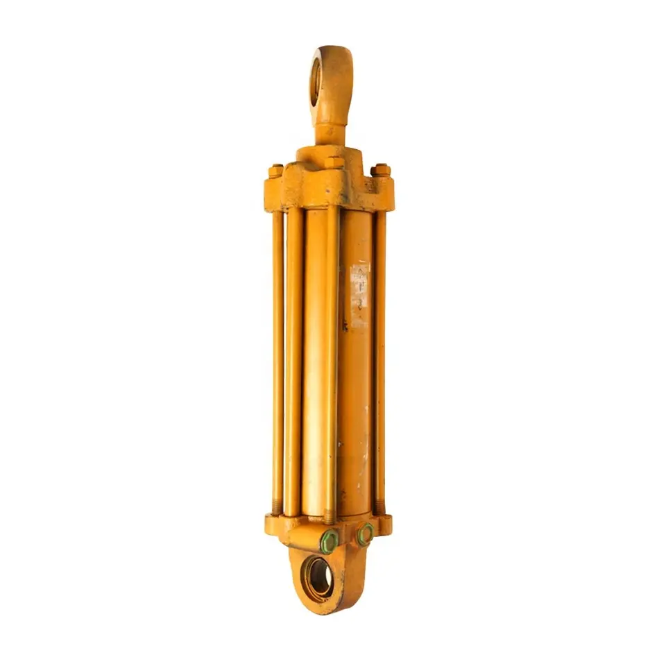
How does a lift cylinder handle variations in fluid pressure and flow rate?
A lift cylinder is designed to handle variations in fluid pressure and flow rate in order to ensure smooth and controlled operation. Here’s an explanation of how lift cylinders handle these variations:
1. Fluid Pressure:
Lift cylinders are typically part of a hydraulic system that utilizes pressurized fluid to generate the necessary force for lifting. The lift cylinder is designed to withstand varying fluid pressure levels. When the fluid pressure is increased, the lift cylinder can handle the additional force exerted on its piston. Conversely, when the fluid pressure decreases, the lift cylinder adjusts accordingly and maintains its functionality.
2. Flow Rate:
The flow rate of hydraulic fluid determines the speed at which the lift cylinder extends or retracts. Lift cylinders are designed to accommodate variations in flow rate. By controlling the flow rate of the hydraulic fluid through the use of control valves or flow control devices, operators can adjust the speed of the lift cylinder’s movement. This allows for precise and controlled lifting operations.
3. Control Valves:
Control valves are an integral part of the hydraulic system that regulates the fluid pressure and flow rate. Lift cylinders are often equipped with control valves that enable operators to control the movement of the cylinder by adjusting the pressure and flow of the hydraulic fluid. These valves can be manually operated or automated, providing flexibility in handling variations in fluid pressure and flow rate.
4. Cylinder Design:
Lift cylinders are designed to be robust and durable, capable of withstanding variations in fluid pressure and flow rate. The cylinder’s construction and materials are selected to ensure optimal performance under different operating conditions. Seals and other components within the lift cylinder are designed to maintain their functionality and prevent leakage, even when subjected to changes in fluid pressure and flow rate.
5. Fluid Control Systems:
In more advanced lift cylinder systems, fluid control systems may be employed to handle variations in fluid pressure and flow rate. These systems can include pressure relief valves, flow control valves, or proportional valves. Pressure relief valves protect the lift cylinder and the hydraulic system from excessive pressure, while flow control valves regulate the flow rate of the hydraulic fluid. Proportional valves provide precise control over both pressure and flow, allowing for fine-tuning of the lift cylinder’s movement.
In summary, lift cylinders are designed to handle variations in fluid pressure and flow rate to ensure smooth and controlled lifting operations. With the use of control valves, robust cylinder design, and fluid control systems, lift cylinders can adapt to changes in fluid pressure and flow rate, providing reliable and efficient performance.
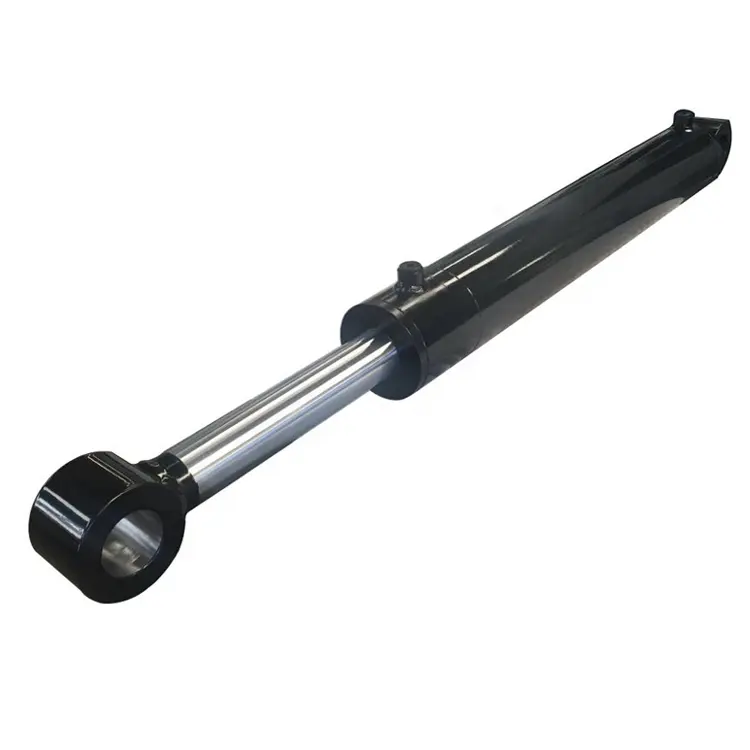
How does a lift cylinder handle variations in hydraulic seal technology?
A lift cylinder is designed to accommodate variations in hydraulic seal technology. Here’s an explanation of how lift cylinders handle these variations:
1. Seal Types:
Hydraulic seal technology offers various types of seals, including O-rings, lip seals, V-rings, and wipers. Lift cylinders are designed to incorporate different seal types based on the specific requirements of the application. The selection of seal types depends on factors such as pressure, temperature, fluid compatibility, and environmental conditions. Lift cylinders are manufactured with the necessary seal grooves and configurations to accommodate these variations in seal types.
2. Seal Materials:
Hydraulic seals are manufactured using different materials, such as rubber, polyurethane, PTFE (polytetrafluoroethylene), and various composite materials. Each material offers specific properties, including resistance to wear, temperature, chemicals, and extrusion. Lift cylinders are engineered to work with different seal materials, ensuring compatibility and optimal performance. The cylinder design takes into account the specific characteristics and requirements of the seal materials used.
3. Seal Profiles and Dimensions:
Hydraulic seals come in various profiles and dimensions to suit different applications and equipment. Lift cylinders are designed with corresponding seal grooves and dimensions to accommodate the specific seal profiles. The seal profiles may include standard shapes such as U-cups, piston seals, rod seals, and specialized profiles for specific sealing requirements. Lift cylinders are manufactured with precise tolerances to ensure proper installation and sealing effectiveness.
4. Sealing Performance and Efficiency:
Lift cylinders are engineered to provide optimal sealing performance and efficiency. They are designed to minimize leakage and maintain the required hydraulic pressure during operation. The cylinder components, including the piston, rod, and cylinder housing, are precisely machined to ensure a tight fit and prevent bypass of hydraulic fluid. Lift cylinders undergo rigorous testing and quality control measures to verify their sealing performance and efficiency under various operating conditions.
5. Seal Maintenance and Replacement:
Lift cylinders are designed to facilitate seal maintenance and replacement. Over time, hydraulic seals may wear out or degrade due to factors such as usage, environmental conditions, or fluid contamination. Lift cylinders are constructed to allow for easy access to the seals, making maintenance and replacement procedures efficient. This design consideration reduces downtime and ensures the longevity of the lift cylinder’s sealing system.
In summary, lift cylinders are engineered to handle variations in hydraulic seal technology by accommodating different seal types, materials, profiles, and dimensions. Their design ensures optimal sealing performance, efficiency, and ease of maintenance. By incorporating the appropriate seal technology, lift cylinders maintain the integrity of the hydraulic system, prevent leaks, and ensure reliable and efficient operation.
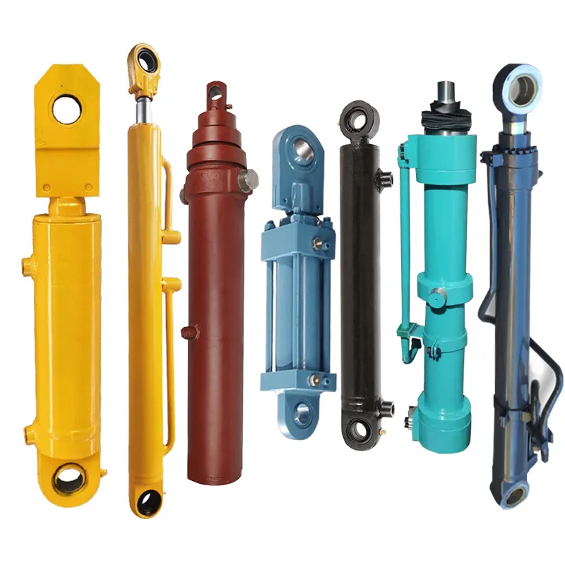
What are the key components of a lift cylinder?
A lift cylinder, also known as a hydraulic lift cylinder or hydraulic lifting cylinder, consists of several key components that work together to enable its functionality. Here’s an explanation of the key components of a lift cylinder:
1. Cylinder Barrel:
The cylinder barrel is a cylindrical hollow tube that forms the main body of the lift cylinder. It provides the housing for the other components and contains the hydraulic fluid, allowing it to flow in and out of the cylinder.
2. Piston:
The piston is a cylindrical component that separates the cylinder barrel into two chambers. It is typically made of metal and has a precise fit within the cylinder barrel. The piston’s movement within the cylinder barrel is crucial for generating the lifting force.
3. Rod:
The rod, also known as the piston rod or plunger rod, is attached to the piston and extends from the cylinder barrel. It serves as a connection point for the load or the mechanism being lifted. The rod transfers the lifting force generated by the piston to the load.
4. Seals:
Seals are essential components that prevent hydraulic fluid leakage and maintain the integrity of the hydraulic system. They are located between the cylinder barrel and the piston, as well as around the rod. Seals ensure that the hydraulic fluid remains contained within the cylinder and prevent external contaminants from entering the system.
5. Hydraulic Fluid:
Hydraulic fluid, such as oil or synthetic fluid, is the medium used to transmit force within the lift cylinder. It is stored within the cylinder barrel and flows in and out of the cylinder to generate the necessary pressure for lifting and lowering operations.
6. Control Valve:
A control valve is a crucial component that regulates the flow of hydraulic fluid into and out of the lift cylinder. It determines the direction and amount of fluid entering the cylinder, allowing for precise control of the lifting and lowering operations. The control valve is typically operated by the operator or controlled automatically in hydraulic systems.
These key components work together to enable the operation of the lift cylinder. When hydraulic fluid is supplied to the appropriate chamber of the cylinder, it applies pressure on the piston, causing it to move and extend or retract the rod. This movement generates the lifting or lowering force required for a specific application.


editor by CX 2023-11-23














