
TECHNICAL GUIDE · POSITION SENSING · HYDRAULIC LIFT CYLINDERS
Lift Cylinder Position
Sensor Integration
Encoder · Magnetostrictive · LVDT
Integrating position feedback into a hydraulic lift cylinder transforms it from a simple force actuator into a precision positioning device capable of closed-loop position control with accuracies down to ±0.1 mm over metre-long strokes. The choice of sensor technology — magnetostrictive transducer, linear encoder, LVDT, potentiometer, or string encoder — determines the system’s accuracy, environmental robustness, wiring complexity, and cost. This guide covers the integration methods, technology selection criteria, and commissioning requirements for position feedback on industrial hydraulic lift cylinders.
Linear Encoder
Closed-Loop Control
LIFT CYLINDERS · POSITION SENSING ENGINEERING · JULY 2026
REFERENCE · POSITION SENSOR TECHNOLOGY COMPARISON
MAGNETOSTRICTIVE
±0.1 mm
Best accuracy and reliability for internal rod installation — no wear, immune to oil contamination, 0–5 m stroke range
LINEAR ENCODER
±0.01 mm
Highest accuracy for external installation — glass or steel scale, requires clean environment and mechanical alignment
STRING POT
±0.5–1 mm
Lowest cost external option — spring-retracted cable measures extension length; adequate for most industrial closed-loop applications
LVDT
±0.05 mm
High accuracy, frictionless, short stroke — used in test rigs and high-precision positioning applications up to 300 mm stroke
अनुभाग 01
Why Add Position Sensing to a Lift Cylinder
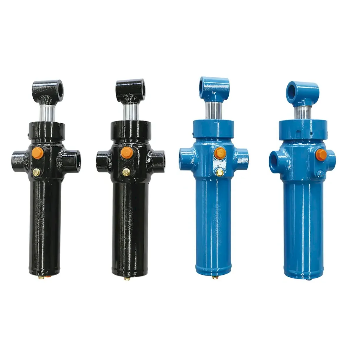
A hydraulic lift cylinder without position feedback operates in open-loop mode — the control system commands a valve opening and trusts that the cylinder moves to the intended position based on flow rate and time. Open-loop control is adequate for many lifting applications. However, several industrial requirements demand closed-loop position control:
PRECISION POSITIONING
Automotive assembly line lift cylinders that must present parts at a precise height to robotic welders or assemblers — repeatability of ±0.5 mm or better required. Without position feedback, thermal drift, load variation, and oil viscosity changes cause the open-loop position to vary by ±5–15 mm from cycle to cycle.
सिंक्रनाइज़ेशन
Multiple-cylinder synchronised lift systems — gantry hoists, ship section jacking frames, press platens — require each lift cylinder to remain within a defined height tolerance of the others throughout the lift. Position sensors on each cylinder provide the feedback needed to adjust individual cylinder flow in real time and maintain synchronisation.
SAFETY MONITORING
Platform height monitoring on aerial work platforms (AWP), dock levellers, and scissors lifts — the position sensor provides continuous feedback to the control system confirming the platform is at the commanded height. A deviation beyond a defined threshold triggers an alarm or automatic correction before the height error becomes a safety issue.
PROCESS AUTOMATION
CNC-controlled hydraulic press brakes, forming machines, and injection moulding lift cylinders require position feedback to generate accurate position profiles — the control system must know exactly where the piston is at each moment of the forming or moulding cycle to produce consistent parts.
अनुभाग 02
Magnetostrictive Transducers — Internal Rod Installation
The magnetostrictive linear position transducer is the most widely used position sensor for integrating into hydraulic lift cylinders — it is installed inside a hollow bored rod, completely enclosed within the hydraulic environment and protected from all external contamination. The operating principle uses a torsional wave propagating along a ferromagnetic wire: a current pulse travels along the wire, and a position magnet on the piston generates a torsional stress wave at the magnet location that travels back to the sensor head at a known speed. The time between current pulse and torsional wave arrival gives absolute position to ±0.1 mm without any moving parts or wear surfaces.
ROD BORE
SPEC
The lift cylinder rod must be hollow-bored to accommodate the magnetostrictive tube. Standard tube diameters: 10 mm OD for stroke up to 2 000 mm; 14 mm OD for stroke up to 4 000 mm. The bore must be sealed at the rod tip with an end plug, and the sensor cable exits through a side port in the rod just inside the gland — an oil-tight gland seal around the cable is essential to prevent oil seeping out through the sensor cable path.
POSITION
MAGNET
A ring magnet is installed in the piston bore concentric with the magnetostrictive tube. The magnet must be non-magnetic to the hydraulic circuit — rare-earth magnets (SmCo or NdFeB) are typically housed in a non-magnetic stainless steel carrier ring. The position of this magnet on the piston is the reference datum — it must be precisely located relative to the piston face to give accurate position readings from the cylinder’s mechanical end position.
OUTPUT
SIGNALS
Standard magnetostrictive transducer outputs for lift cylinder position applications: 4–20 mA analogue (most common for industrial PLCs); 0–10 V analogue; SSI (synchronous serial interface) for high-resolution digital position; CANopen or Profibus for network-connected systems. The output must be specified to match the receiving PLC or motion controller input — an incorrect output type cannot be reconfigured in the field without replacing the transducer electronics.
Hydraulic lift cylinders with factory-installed magnetostrictive position transducers — hollow-bored rod, integral ring magnet, cable gland, and choice of 4–20 mA or SSI output — are available from the लिफ्ट सिलेंडर product range. Factory installation ensures correct bore tolerances, magnet positioning, and cable routing that is difficult to achieve in field retrofits.
अनुभाग 03
External Sensors — String Pot, Linear Encoder and LVDT
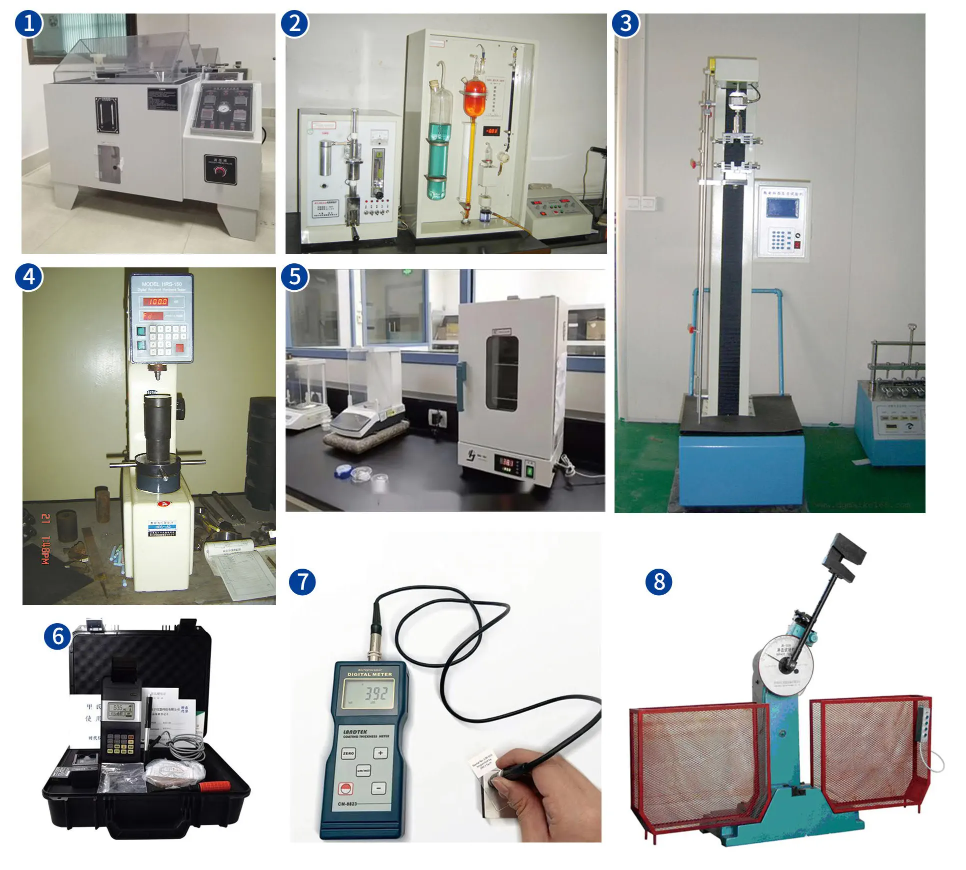
External position sensors are mounted adjacent to the lift cylinder rather than inside it. They are suitable when the cylinder rod cannot be bored (too small, or an existing cylinder without internal access), when the application requires higher accuracy than a magnetostrictive transducer can provide, or when retrofitting position sensing to an existing cylinder without disassembly:
| SENSOR TYPE | ACCURACY | MAX STROKE | ENVIRONMENT | BEST FOR |
|---|---|---|---|---|
| String potentiometer | ±0.5–2 mm | Up to 5 m | IP65 standard | Retrofit to existing lift cylinders; moderate accuracy closed-loop industrial |
| Optical linear encoder | ±0.005–0.05 mm | Up to 30 m | Requires clean environment | Machine tool hydraulic axis; clean-room industrial; highest accuracy requirement |
| Magnetic encoder strip | ±0.1–0.5 mm | Up to 50 m | IP67, tolerates oil mist | Long-stroke industrial lift cylinders; outdoor mobile equipment |
| LVDT (inductive) | ±0.01–0.05 mm | Up to 300 mm | Excellent — sealed, no contact | Short-stroke test and calibration cylinders; high-precision positioning systems |
अनुभाग 04
Closed-Loop Control Architecture
A position-controlled hydraulic lift cylinder requires four components working together: the lift cylinder itself, the position sensor, a proportional or servo hydraulic valve, and a motion controller or PLC with a position control algorithm. The signal chain and tuning approach determine the achievable accuracy and dynamic response:
CLOSED-LOOP POSITION CONTROL — SIGNAL CHAIN
CONTROLLER
PLC / motion
controller
→
PROPORTIONAL
वाल्व
4/3 proportional
directional valve
→
लिफ्ट सिलेंडर
Position-sensored
हाइड्रोलिक एक्चुएटर
→
POSITION SENSOR
Magnetostrictive
or external
↩
PROPORTIONAL VALVE
A standard on/off directional valve cannot provide proportional flow control — a proportional or servo valve with linear opening characteristic relative to the input signal is required. Proportional valves are adequate for most industrial lift cylinder position applications; servo valves are used where the dynamic response requirement exceeds the proportional valve’s bandwidth (typically above 20 Hz).
PID TUNING
The position control loop uses a PID (proportional-integral-derivative) algorithm to minimise position error. Hydraulic lift cylinders have inherent nonlinearities — compressibility of the oil, stick-slip at the rod seal, and load-dependent pressure drop — that must be compensated in the PID tuning. Start with a low gain (P=2, I=0.1, D=0) and increase P until oscillation begins, then reduce by 30% and introduce I to eliminate steady-state error.
POSITION ACCURACY
Achievable position accuracy with a magnetostrictive sensor and a quality proportional valve: ±0.5 mm for a standard industrial application under constant load. With a servo valve and a faster control loop: ±0.1–0.2 mm. Thermal drift of the hydraulic oil is typically the limiting factor for sustained accuracy — a 10°C temperature rise expands the oil and shifts the zero of a non-absolute sensor.
For industrial lift cylinder systems requiring integrated position control with proportional valve, PLC interface, and magnetostrictive position transducer as a complete assembly, the औद्योगिक इंजीनियरिंग हाइड्रोलिक सिलेंडर range provides configurations with factory-fitted transducers and the mechanical interface drawings required for PLC integration.
अनुभाग 05
Sensor Technology Selection Guide
The sensor selection decision for a lift cylinder position feedback application can be simplified to three questions: Where can the sensor be physically installed? What accuracy is required? What is the operating environment?
CASE A
New lift cylinder, harsh environment, stroke 200–4 000 mm, accuracy ±0.5 mm or better: Magnetostrictive transducer internal to hollow rod. Best choice — no external parts to damage, no wear, oil-immune, absolute position output. Factory installation preferred.
CASE B
Existing lift cylinder, retrofit without disassembly, accuracy ±1–2 mm: External string potentiometer. Lowest retrofit cost, easiest installation. Attach mounting bracket to cylinder body and cable end to rod clevis.
CASE C
Machine tool axis, clean environment, accuracy ±0.01–0.05 mm: External optical linear encoder on protected scale. Highest accuracy available — requires mechanical mounting in a clean, protected channel alongside the lift cylinder axis.
CASE D
Short stroke ≤ 300 mm, precision calibration or test application: LVDT (Linear Variable Differential Transformer). Frictionless, no wear, excellent linearity and repeatability for short-stroke precision applications including material testing machines and calibration lift cylinders.
अनुभाग 06
Installation and Commissioning Requirements
Correct installation and commissioning of a position-sensored lift cylinder determines whether the system achieves its specified accuracy. The most common commissioning errors that prevent a position-sensored lift cylinder from meeting its specification are:
त्रुटि 1
Incorrect zero offset. The sensor’s zero position (output = 0 mm) must be set to correspond to the lift cylinder’s mechanical retracted position. If the zero is set at a point mid-stroke during commissioning, all subsequent position readings will be offset by the distance between the actual retracted position and the set-zero point. Verify zero with the piston fully retracted against the cap-end.
त्रुटि 2
Sensor cable routing near EMI sources. Magnetostrictive transducer signal cables must be routed away from power cables, frequency converters, and contactor panels — EMI interference causes position reading noise that appears as apparent oscillation of the lift cylinder position even when it is stationary. Use shielded cable with the shield earthed at only one end (the controller end).
त्रुटि 3
Air in the lift cylinder circuit. Air trapped in the lift cylinder hydraulic circuit causes the piston to “slip” — the oil compresses before the piston moves, then decompresses when the valve closes, moving the piston without a valve signal. This produces erratic position feedback that makes the closed-loop controller hunt continuously. Bleed all air from the circuit thoroughly before commissioning the position control loop.
त्रुटि 4
Proportional valve at incorrect null offset. A proportional directional valve has an adjustable null (the input signal at which the valve is exactly closed). If the null is not set correctly, the valve passes a small flow even when commanded to zero — the lift cylinder drifts slowly from its commanded position, appearing to the control loop as a persistent position error that drives the controller to apply a continuous correction signal. Set the null precisely using the valve manufacturer’s procedure with the lift cylinder hydraulic circuit pressurised before running any position control commissioning test.
तकनीकी संबंधी सामान्य प्रश्न
Position Sensing Questions
प्रश्न 01
Our position-sensored lift cylinder shows oscillation at the target position — the piston hunts back and forth by ±3 mm. What is causing this?
Position hunting around the target is the classic symptom of excessive proportional gain (P) in the PID controller — the controller is overcorrecting the error and overshooting in the opposite direction repeatedly. The fix is to reduce the P gain until the oscillation stops, then re-tune. A secondary cause is stick-slip at the lift cylinder rod seal — the piston is stationary (seal friction holds it), the controller continues applying a correction signal (because there is still position error), pressure builds, the seal suddenly breaks free and the piston overshoots, the controller reverses, and the cycle repeats. Stick-slip can be reduced by upgrading the rod seal to a lower-friction specification (PU 88 Shore A instead of NBR 90), or by adding a small dither signal to the valve command to keep the valve and piston in micro-motion. If neither P-gain reduction nor seal upgrade resolves the hunting, check that the proportional valve null is correctly set — a valve passing flow at null drives the lift cylinder into a pressure imbalance that the position controller must continuously fight.
प्रश्न 02
Can a magnetostrictive sensor be retrofitted into a lift cylinder that was not originally designed for one?
Yes, but it requires the lift cylinder rod to be removed and bored on a lathe to create the central bore for the transducer tube, and the piston must be machined to accept the ring magnet carrier. The rod end plug and cable exit gland must also be fitted. This is practical for large-bore cylinders with rods of sufficient diameter to accept the bore without compromising the rod’s structural cross-section — a minimum rod diameter of approximately 50 mm is needed for a 10 mm transducer tube with adequate steel wall remaining. For smaller rods, an external string potentiometer is the more practical retrofit option. The decision whether to retrofit or replace with a factory-sensored lift cylinder depends on the remaining service life of the existing cylinder — if the rod chrome and bore are in good condition, a retrofit sensor is cost-effective; if rebuilding is needed anyway, a new factory-integrated unit with magnetostrictive sensor is the better choice.
प्रश्न 03
We need to synchronise four lift cylinders to ±2 mm across a 3 000 mm span — is this achievable with standard proportional valves and magnetostrictive sensors?
Yes — ±2 mm synchronisation across four cylinders with magnetostrictive sensors and proportional valves is achievable and is a standard specification for gantry hoists, ship section jacking frames, and press platen levelling systems. The control architecture uses one lift cylinder as the master and treats the other three as slaves — each slave receives its position target from the master and drives its valve to minimise position error. The master-slave architecture is simpler to tune than a fully independent PID on each axis because the slaves do not need to know the absolute position, only the relative error to the master. In practice, the achievable synchronisation with standard proportional valves is ±1–3 mm depending on load variation and oil temperature stability. If tighter synchronisation (±0.5 mm) is required, servo valves and a faster control loop are needed. A hydraulic flow divider block in addition to the electronic synchronisation provides a mechanical backstop against synchronisation error if the electronic system faults — combining electronic and mechanical synchronisation is best practice for heavy-lift applications.
प्रश्न 04
The magnetostrictive sensor in our lift cylinder gives a correct reading at low speed but loses accuracy at high piston velocity. What is causing this?
Position accuracy degradation at high piston velocity typically indicates a controller scan rate that is too slow relative to the velocity — the controller is sampling the position at intervals during which the lift cylinder has moved more than the allowable error. For example, a controller scanning at 10 ms intervals with a piston moving at 0.5 m/s will see the position change by 5 mm between scans — if the control loop tries to correct a 5 mm error in one scan cycle, it will overshoot. The fix is either to increase the controller scan rate (many PLCs can be configured for faster scan on specific tasks), or to implement a velocity feedforward term in the control algorithm that anticipates the piston’s position based on commanded velocity and only uses the sensor for error correction rather than as the primary position reference. A third possibility is that the magnetostrictive sensor’s update rate is slower than the controller scan rate — verify that the sensor’s specified update rate (typically 1–5 ms) is faster than the PLC scan cycle. If the sensor update rate is the limiting factor, a sensor with a faster update rate or a digital SSI interface (which has better update speed characteristics than analogue 4–20 mA) should be specified for the replacement lift cylinder.
POSITION-SENSORED LIFT CYLINDER SUPPLY
Need a Lift Cylinder with Position Feedback?
Lift cylinders with factory-integrated magnetostrictive transducers — hollow rod, ring magnet, cable gland, and 4–20 mA or SSI output — are available for all standard bore sizes. Provide the bore, stroke, accuracy requirement, and output interface to receive a specification.
संपादक: सीएक्सएम














