
Product Description
Welcome To CHINAMFG HYDRAULICS!
Product Description
Product Parameters
Technical Data
| Cylinder Type | Mill type, Head Bolted, Base Welded |
| Bore Diameter | Up to 2500mm |
| Rod Diameter | Up to 2000mm |
| Stroke Length | Up to 20,000mm |
| Piston Rod Material | AISI 1045, AISI 4140, AISI 4340, 20MnV6, Stainless steel 2Cr13 or 1Cr17Ni2 |
| Rod Surface Treatment | Hard chrome plated, Chrome/Nickel plated, Ceramic coated |
| Tube Material | Carbon steel AISI1045 or ST52.3, Alloy steel AISI4140 or 27SiMn |
| Tube Surface Painting | Colors according to RAL and thickness according to customer needs |
| Mounting Type | Clevis, Cross tube, Flange, Trunnion, Tang, Thread |
| Design Pressure | Up to 40Mpa |
| Seal Kits Type | PARKER, MERKEL, HALLITE, NOK, TRELLEBORG |
| Quality Assurance | 1 year |
| Certificate | SGS, BV, ABS ,GL, DNV etc. |
| Application | Mobile Equipment,Cement Mill, steel mill, Hydraulic press, etc. |
Quality Assurance
| Quality Process | Our quality management system is certified to ISO 9001 |
| Quality control standards include material records, process control plans, | |
| Manufacturing approvals and inspection data | |
| Testing Standards | All products undergo 100% pressure testing 1.5 times the maximum allowable working pressure or to customer specifications |
| Static and dynamic pressure testing. | |
| Ultraviolet leak detection technology. | |
| Non-destructive testing. | |
| Fluid Cleanliness | Real-time monitoring and test phase documentation |
| Independent sampling and oil diagnostic control |
Finished Product Display
Application Area
Company Profile
FLUTEC HYDRAULICS is an expert at designing and manufacturing a broad range of custom engineered hydraulic cylinders and cylinder systems as well as custom engineered press bolster plates. We are proud to offer superior quality products and services for various applications including industrial, construction, mobile, agricultural, mining, steel mill, hydraulic press, etc. Our highly skilled team and modern technical facilities allow us to manufacture large bore hydraulic cylinders and long stroke hydraulic cylinders with 100% confidence and assurance.
We understand our customers need dependable quality and excellent services with affordable cost to stay ahead in today’s highly competitive market. CHINAMFG HYDRAULICS can meet those requirements with our robust, efficient and long life products together with prompt services.
To be mentioned, our sales team is strictly trained both in technology and language. They are full of experiences in fluid power and machinery. We are glad to personally visit our customers to work better.
FAQ
Q1: What does your company do?
A: we are a supplier of high-quality hydraulic products including Hydraulic Cylinder,Honed Tube,Chromed Rod,Machined Platen,Cylinder Parts, and other components.
Q2:Are you a manufacturer or trading company?
A: We are a manufacturer.
Q3: Are you able to make Non-standard or customized products?
A: Yes, we can. Custom-made Hydraulic Cylinder is our key business.
Q4: How long is your delivery time?
A: The delivery time for customized products is 30 working days.But it also depends on the product requirements and quantity.
Q5: Do you provide samples?
A: No, we don’t provide samples.
Q6: What are your payment terms?
A: T/T/ or L/C or D/P. If you have any questions, please feel free to contact us.
Q7: What are your After-sales services?
A: Before shipment, Each individual product will be strictly inspected on our factory QC Process System. In addition, We have a Customer Service team to respond to customers’ questions within 12 hours. Being helpful in solving customers’ problems is always our goal.
| Certification: | GS, RoHS, ISO9001, Dnv, SGS, BV, ABS, Gl |
|---|---|
| Pressure: | High Pressure |
| Work Temperature: | Normal Temperature |
| Acting Way: | Double Acting |
| Working Method: | Straight Trip |
| Adjusted Form: | Regulated Type |
| Customization: |
Available
|
|
|---|
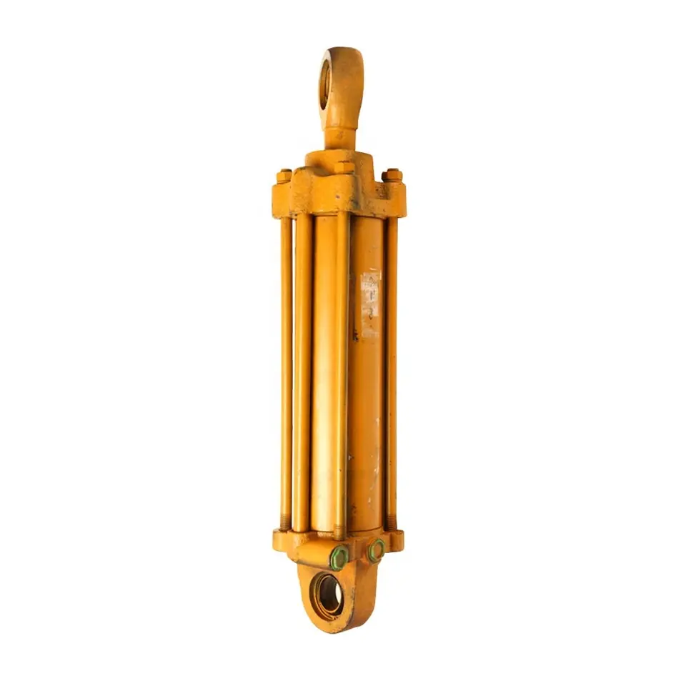
How does a lift cylinder handle variations in fluid pressure and flow rate?
A lift cylinder is designed to handle variations in fluid pressure and flow rate in order to ensure smooth and controlled operation. Here’s an explanation of how lift cylinders handle these variations:
1. Fluid Pressure:
Lift cylinders are typically part of a hydraulic system that utilizes pressurized fluid to generate the necessary force for lifting. The lift cylinder is designed to withstand varying fluid pressure levels. When the fluid pressure is increased, the lift cylinder can handle the additional force exerted on its piston. Conversely, when the fluid pressure decreases, the lift cylinder adjusts accordingly and maintains its functionality.
2. Flow Rate:
The flow rate of hydraulic fluid determines the speed at which the lift cylinder extends or retracts. Lift cylinders are designed to accommodate variations in flow rate. By controlling the flow rate of the hydraulic fluid through the use of control valves or flow control devices, operators can adjust the speed of the lift cylinder’s movement. This allows for precise and controlled lifting operations.
3. Control Valves:
Control valves are an integral part of the hydraulic system that regulates the fluid pressure and flow rate. Lift cylinders are often equipped with control valves that enable operators to control the movement of the cylinder by adjusting the pressure and flow of the hydraulic fluid. These valves can be manually operated or automated, providing flexibility in handling variations in fluid pressure and flow rate.
4. Cylinder Design:
Lift cylinders are designed to be robust and durable, capable of withstanding variations in fluid pressure and flow rate. The cylinder’s construction and materials are selected to ensure optimal performance under different operating conditions. Seals and other components within the lift cylinder are designed to maintain their functionality and prevent leakage, even when subjected to changes in fluid pressure and flow rate.
5. Fluid Control Systems:
In more advanced lift cylinder systems, fluid control systems may be employed to handle variations in fluid pressure and flow rate. These systems can include pressure relief valves, flow control valves, or proportional valves. Pressure relief valves protect the lift cylinder and the hydraulic system from excessive pressure, while flow control valves regulate the flow rate of the hydraulic fluid. Proportional valves provide precise control over both pressure and flow, allowing for fine-tuning of the lift cylinder’s movement.
In summary, lift cylinders are designed to handle variations in fluid pressure and flow rate to ensure smooth and controlled lifting operations. With the use of control valves, robust cylinder design, and fluid control systems, lift cylinders can adapt to changes in fluid pressure and flow rate, providing reliable and efficient performance.
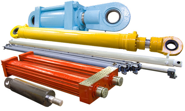
Can Lift Cylinders Be Used in Waste and Recycling Equipment?
Yes, lift cylinders are commonly used in waste and recycling equipment to facilitate various operations involved in waste management and recycling processes. These cylinders play a crucial role in lifting, compacting, and handling waste materials efficiently and effectively. Here’s a detailed explanation of how lift cylinders can be used in waste and recycling equipment:
- Lifting and Dumping:
- Compacting:
- Container Handling:
- Baling:
- Sorting and Separation:
- Feeding and Conveying:
Waste and recycling equipment often require the lifting and dumping of containers or bins to empty their contents into larger collection vehicles or processing systems. Lift cylinders are utilized in this process to provide the necessary lifting force and controlled movement. The cylinders are typically integrated into lifting mechanisms, such as automated arms or hydraulic lifts, which securely grip and elevate the containers. The lift cylinders ensure smooth and controlled lifting, allowing the containers to be safely emptied into the desired location.
In waste management, compacting waste materials is essential to optimize space utilization and reduce the frequency of waste collection. Lift cylinders are commonly employed in compactors, including stationary compactors, vertical compactors, and roll-off compactors. These cylinders apply force to compress the waste, reducing its volume and making it more manageable for storage or transportation. The lift cylinders enable the compactor’s compaction plate or ram to exert the necessary pressure, ensuring efficient waste compaction.
Waste and recycling equipment often involve the handling and movement of various containers, such as bins, dumpsters, or roll-off containers. Lift cylinders are used in container handling systems to lift, tilt, or slide these containers for emptying or transportation purposes. The cylinders provide the required lifting force and controlled motion, allowing operators to manipulate the containers with ease. Lift cylinders ensure secure and precise container handling, facilitating the efficient transfer of waste materials from one location to another.
Baling is a common process in recycling facilities where waste materials, such as cardboard, paper, plastics, or metal, are compacted into tightly bound bales for easier storage and transportation. Lift cylinders are integral components of balers, enabling the compression and shaping of the waste materials into bales. The cylinders exert force on the baler ram, which presses the waste materials together, forming tightly compressed bales. Lift cylinders ensure the necessary force and control for effective baling operations in recycling facilities.
In recycling processes, waste materials often need to be sorted and separated based on their type or composition. Lift cylinders can be utilized in sorting and separation equipment to manipulate or lift specific waste items or components. For example, lift cylinders can be employed in conveyor systems or picking stations to raise or tilt materials, facilitating manual or automated sorting. The cylinders enable precise and controlled movements, enhancing the efficiency and accuracy of waste material separation.
Waste and recycling equipment may involve feeding waste materials into processing systems or conveying them between different stages of the recycling process. Lift cylinders can be used to facilitate the feeding and conveying operations by controlling the movement of hoppers, chutes, or conveyor belts. The cylinders provide the necessary force and adjustability to regulate the material flow, ensuring a consistent and controlled feeding or conveying process.
Lift cylinders are versatile components that find wide application in waste and recycling equipment. Whether it’s for lifting and dumping containers, compacting waste, handling containers, baling materials, sorting and separation tasks, or facilitating feeding and conveying operations, lift cylinders contribute to the efficient and effective management of waste materials and recycling processes.
What is a lift cylinder and how does it function in hydraulic systems?
A lift cylinder, also known as a hydraulic lift cylinder or hydraulic lifting cylinder, is a device used in hydraulic systems to generate linear motion and provide lifting force. It is a type of hydraulic actuator that converts hydraulic pressure into mechanical force to lift heavy loads. Here’s an explanation of what a lift cylinder is and how it functions in hydraulic systems:
A lift cylinder consists of a cylindrical barrel, a piston, and a rod. The barrel is a hollow tube that houses the piston and allows fluid to flow in and out. The piston is a cylindrical component that separates the barrel into two chambers. The rod, attached to the piston, extends from the cylinder to connect with the load or the mechanism being lifted.
The lift cylinder operates based on the principles of Pascal’s law, which states that pressure exerted on a fluid in a confined space is transmitted equally in all directions. Here’s how a lift cylinder functions:
1. Extension:
When pressurized hydraulic fluid enters one side of the cylinder (the chamber behind the piston), it applies force on the piston, causing it to move in the direction of the load. This movement extends the rod outward, lifting or pushing the load.
2. Retraction:
Conversely, when the hydraulic fluid is supplied to the other side of the cylinder (the chamber in front of the piston), the pressure differential causes the piston to move in the opposite direction. This retracts the rod, lowering or pulling the load.
3. Control Valve:
The flow of hydraulic fluid into and out of the lift cylinder is controlled by a directional control valve. The valve regulates the direction and amount of fluid entering the cylinder, determining whether the cylinder extends or retracts. This control allows for precise and controlled lifting and lowering of the load.
4. Force and Load Capacity:
The force generated by the lift cylinder is determined by the hydraulic pressure applied to the piston and the effective area of the piston. By increasing or decreasing the hydraulic pressure, the lifting force can be adjusted to meet the specific load requirements.
5. Application:
Lift cylinders are widely used in various hydraulic systems, including hydraulic lifts, cranes, forklifts, dump trucks, and construction equipment. They provide the necessary force to lift heavy objects, perform material handling tasks, and support heavy loads in a controlled and efficient manner.
In summary, a lift cylinder is a hydraulic actuator that converts hydraulic pressure into mechanical force for lifting heavy loads. It functions by utilizing hydraulic fluid pressure to move the piston and extend or retract the rod, enabling the lifting or lowering of the load. The control valve regulates the fluid flow, and the force generated by the lift cylinder is determined by the hydraulic pressure and piston area. Lift cylinders find extensive applications in hydraulic systems across various industries.


editor by CX 2023-10-21














