
ENGINEERING GUIDE · FAILURE ANALYSIS · HYDRAULIC LIFT CYLINDERS
Lift Cylinder Failure Analysis
Root Cause & Rebuild
vs Replace Decision Guide
A hydraulic lift cylinder that fails repeatedly is not a product quality problem — it is a symptom of an unresolved root cause that will destroy every replacement lift cylinder until the underlying condition is corrected. This guide provides a systematic failure analysis methodology: reading the physical evidence left by the failed components, mapping that evidence to specific root causes, determining whether rebuilding or replacing the lift cylinder is the economically correct decision, and implementing the corrective action that prevents the same failure from recurring.
Root Cause Mapping
Rebuild vs Replace
LIFT CYLINDERS · FAILURE ENGINEERING · JULY 2026
REFERENCE · LIFT CYLINDER FAILURE DISTRIBUTION BY ROOT CAUSE
CONTAMINATION
72%
Of all hydraulic lift cylinder failures have contaminated oil as a contributing or primary cause
MISALIGNMENT
14%
Side loading from installation misalignment — primarily rod seal and barrel failures
OVERLOAD
8%
Structural failures from loads exceeding the cylinder’s rated capacity — often from relief valve misconfiguration
MATERIAL / DESIGN
6%
Wrong seal material for fluid type or temperature — typically identified by rapid failure after oil change
РАЗДЕЛ 01
The Failure Analysis Methodology
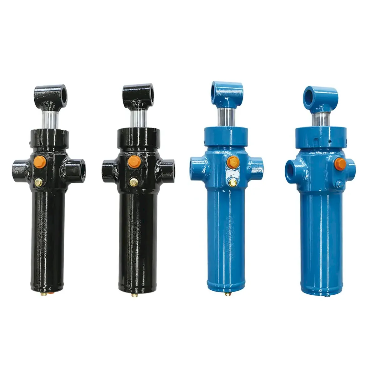
Effective hydraulic lift cylinder failure analysis requires examining five evidence sources in sequence — not just the most visually obvious failed component. The five evidence sources and the sequence in which they should be examined:
① FLUID
Sample the hydraulic oil before draining the lift cylinder — take a mid-circuit sample while the system is still pressurised and send for ISO cleanliness, viscosity, water content, and wear metal analysis. Fluid condition tells you whether contamination, thermal degradation, or chemical incompatibility was a contributing factor before you open the cylinder.
② ROD SURFACE
Before removing the rod from the lift cylinder, photograph the entire rod surface and note the location and pattern of any scoring, pitting, or chrome damage. Scoring concentrated on one quadrant of the rod circumference indicates side loading; scoring uniformly distributed around the circumference indicates abrasive contamination ingress past a failed wiper.
③ SEAL GEOMETRY
Remove the lift cylinder seals carefully and examine the wear pattern on the lip face. Uniform wear across the full sealing lip indicates normal service life or thermal degradation. One-sided wear (heavily worn on one side, less on the opposite) indicates misalignment or side loading. Nibbled or extrusion-damaged lip edge indicates over-pressure or too large a diametric clearance for the seal hardness.
④ BORE SURFACE
Inspect the lift cylinder bore surface with a torch — the original honed cross-hatch pattern should be visible across the full bore length. Polished areas (loss of cross-hatch) indicate high piston seal bypass over the service period. Scoring in the bore running along the cylinder axis indicates hard particle contamination. Corrosion pitting indicates water contamination in the hydraulic oil.
⑤ MOUNTING
Inspect the lift cylinder’s mounting pins, pivot bushings, and bracket faces for wear patterns. Uneven wear on the pin or bushing contact face indicates the cylinder has been running at an angle to its designed axis — the primary cause of rod seal side loading. Measure the pin clearance with feeler gauges and compare to the original specification.
РАЗДЕЛ 02
Reading Rod Seal Failure Evidence
The rod seal is the most frequently failed component in a hydraulic lift cylinder and the one whose failure pattern provides the clearest diagnostic information and the one whose failure pattern provides the clearest diagnostic information. Each failure mode leaves a characteristic pattern on the seal lip, the rod surface, and the gland bore:
ROD SEAL FAILURE PATTERN DIAGNOSIS
Root cause: Abrasive contamination in the hydraulic oil being dragged across the lift cylinder seal lip by the rod on every retraction stroke. Confirmed by ISO oil analysis showing particle counts above class 17/15/12. The wiper seal may also have failed or been over-specified. Corrective action: Replace filter elements; flush circuit; upgrade to 10-micron filtration; replace wiper with metal-scraper type for dusty environments; upgrade rod seal to 92–95 Shore A polyurethane.
Root cause: Side loading from cylinder misalignment, worn pivot pins, or external lateral forces on the rod during operation. The rod is pressing harder on one side of the seal lip than the other, generating asymmetric wear that creates a leak path on the less-pressed side. Corrective action: Measure and correct mounting alignment before installing replacement seal; replace worn pivot bushings; verify that no external lateral forces act on the rod during the machine’s operating cycle.
Root cause: Sustained operating temperature above the seal material’s rated maximum — the elastomer oxidises, loses elasticity, and cracks under the cyclic compression of each rod stroke. Common on NBR seals when oil temperature exceeds 90°C or when the lift cylinder operates in hot-climate environments without adequate cooling. Corrective action: Measure oil temperature at the gland entry during normal operation; if above 80°C, upgrade to FKM seals and/or install an oil cooler; switch to ISO 68 oil grade in hot-climate installations.
Root cause: Chemical incompatibility between the seal elastomer and the hydraulic fluid — the fluid causes the elastomer to swell beyond its designed compression range, extruding from the gland groove and failing. Classic presentation is failure within 4–8 weeks of a fluid change. Corrective action: Identify the new fluid type (check safety data sheet); select compatible seal material (PTFE or FKM for phosphate-ester, EPDM for ester/water-glycol, NBR or PU for mineral oil); ensure all future seal kits match the fluid specification.
РАЗДЕЛ 03
Piston Seal and Internal Bypass Failures
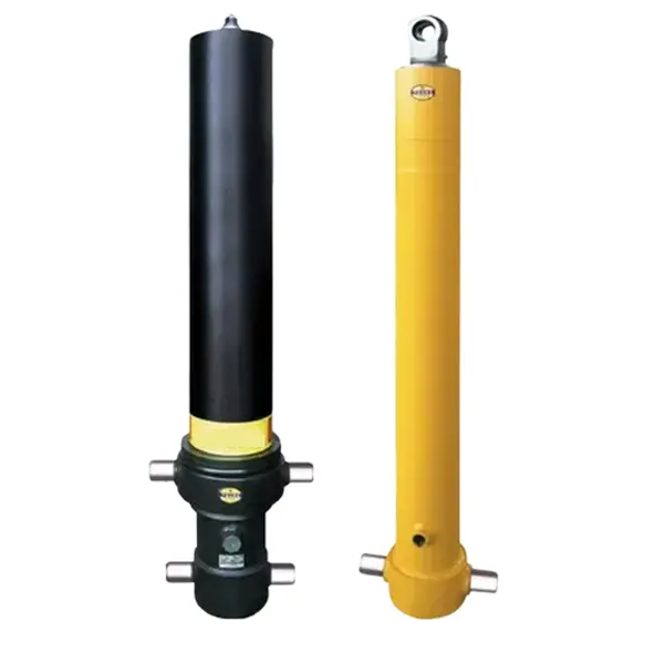
Lift cylinder piston seal failure manifests differently from rod seal failure — there is no visible external leak. Instead, piston seal bypass appears as operational symptoms: the lift cylinder extends slowly under load even with adequate pump flow, the cylinder drifts downward slowly with all valves closed, or the lift cylinder cannot reach full rated pressure. The physical evidence inside the disassembled lift cylinder confirms the diagnosis:
EVIDENCE: POLISHED BORE
Appearance: Mirror-finish areas on the bore surface, loss of original cross-hatch honing pattern. Root cause: High-cycle friction from an undersized or over-compressed piston seal, or a bore that has been run dry due to oil starvation. Действие: If bore surface is polished but not scored, re-hone and fit new seal. If scored, replace the lift cylinder barrel.
EVIDENCE: EXTRUDED SEAL FRAGMENTS
Appearance: Nibbled edge on the piston seal; fragments of seal material found in the hydraulic oil filter or reservoir. Root cause: Diametric clearance between piston and bore is too large for the seal material hardness at operating pressure — the seal extrudes into the gap and breaks off. Действие: Measure bore diameter; if clearance exceeds seal manufacturer’s specification, upgrade to harder backup-ring-supported seal.
EVIDENCE: AXIAL SCORING IN BORE
Appearance: Long scratch marks running parallel to the cylinder axis. Root cause: Hard particle contamination (metal chips, weld spatter, grit) trapped between the piston seal and bore during a previous assembly or ingested through a failed port seal. Действие: Do not re-use the barrel — axial scoring cannot be adequately honed out. Replace entire lift cylinder or re-sleeve the barrel. Trace and eliminate the particle source.
РАЗДЕЛ 04
Structural Failures — Rod, Barrel and Weld
Structural lift cylinder failures — bent rods, split barrels, cracked end-cap welds — are less common than seal failures but more serious in consequence. A structural failure during loaded operation can cause sudden, uncontrolled load release. Each structural failure type has a characteristic cause:
| ТИП ОТКАЗА | PHYSICAL EVIDENCE | PRIMARY CAUSE | CORRECTIVE ACTION |
|---|---|---|---|
| ROD BEND | Permanent bend visible in extended rod; gland score marks on one side | Side load exceeding rod’s column strength — either misalignment or stroke-to-diameter ratio too large for the load | Replace rod; correct alignment; specify heavier rod diameter if ratio >10:1 |
| BARREL SPLIT | Axial crack in barrel wall; catastrophic oil loss; often occurs at end-cap transition zone | Sustained over-pressure from blocked or incorrectly set relief valve; or fatigue from repeated pressure cycling above working pressure | Replace lift cylinder; verify and correct relief valve setting; check for pressure spike source |
| END-CAP WELD CRACK | Oil weeping at barrel-to-end-cap joint; crack visible under penetrant testing | Fatigue cracking from vibration, pressure cycling, or shock loads — common on poorly supported cylinders with long cantilever installations | Replace; add intermediate support or damping if vibration is present |
| ROD THREAD FAILURE | Stripped or sheared rod end thread; sudden disengagement of load | Torque overload from incorrect installation; thread corrosion reducing effective cross-section; incorrect thread specification for the load | Specify thread to ASME or DIN standards for the load; use locking compound; apply anti-seize to stainless threads |
РАЗДЕЛ 05
Rebuild vs Replace Decision Framework
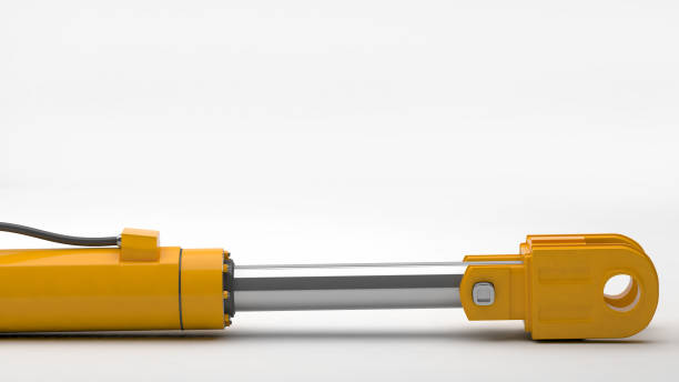
The rebuild-vs-replace decision is an economic calculation, not a philosophical one. Use the condition of the rod and barrel to determine the correct path:
✔ REBUILD — ECONOMICAL
✓
Rod chrome >15 μm remaining — no deep scoring
✓
Bore within honing specification — cross-hatch visible
✓
End-cap welds intact — no cracking
✓
Seal-only failure with clean oil — contamination eliminated
Expected rebuild cost: 25–40% of replacement
⚠ REBUILD WITH MACHINING
~
Rod chrome 5–15 μm — requires re-chroming
~
Bore polished but not scored — can be re-honed
✓
Barrel structurally intact
✓
Large bore (>100 mm) — machining cost justified
Expected rebuild cost: 45–65% of replacement
✗ REPLACE — ECONOMICAL
✗
Rod <5 μm chrome or deep scoring
✗
Bore scored axially or beyond honing tolerance
✗
Bent rod or cracked barrel/weld
✗
Standard bore (≤80 mm) — replacement from stock cheaper than machining
Rebuild would exceed 70–80% of replacement cost
Standard bore replacement lift cylinders for the most common industrial and mobile applications are available from stock in the подъемный цилиндр range — typically a faster and more predictable outcome than a rebuild with machining when the cylinder was a standard specification. For non-standard bore, stroke, or mounting configurations where a rebuild is the only practical option, the гидравлический цилиндр промышленного назначения range covers the widest range of custom-specification options.
РАЗДЕЛ 06
Corrective Actions by Root Cause
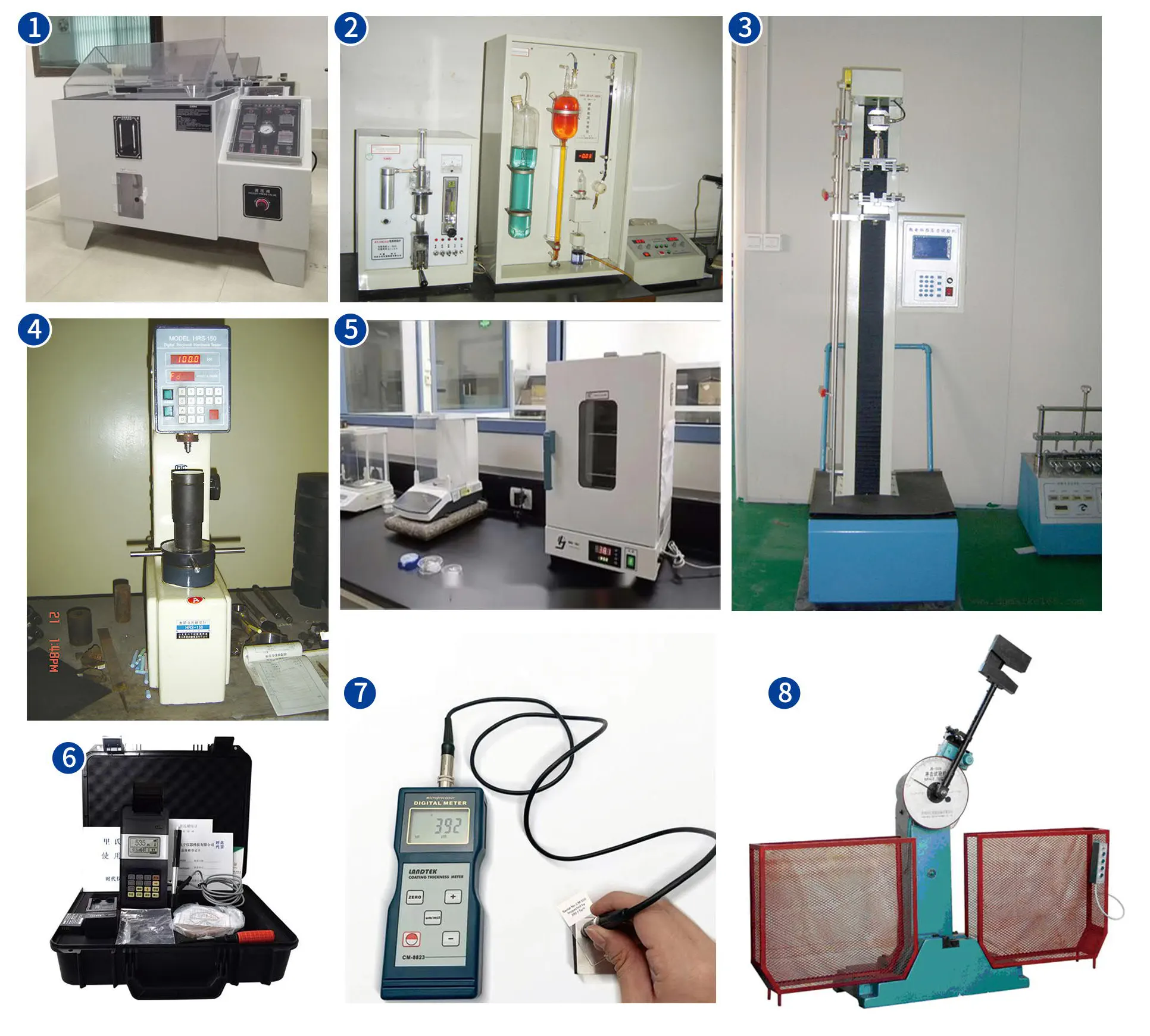
Once the root cause is identified, the corrective action must address the cause — not just replace the failed component. A lift cylinder replaced without addressing the root cause will fail again, typically in a shorter time than the original because the replacement is installed into the same adverse conditions that destroyed the first unit.
▷
Flush the entire hydraulic circuit — not just the lift cylinder — with clean flushing oil before refilling
▷
Replace all filter elements with a higher-grade (lower micron) specification: upgrade from 25-micron to 10-micron if not already at that level
▷
Identify the contamination entry point: damaged reservoir breather, open fill cap, worn pump generating metal particles, or ground ingress through a failed wiper seal
▷
Verify ISO class 16/14/11 or better by oil sample analysis before returning the rebuilt or replacement lift cylinder to service
▷
Measure the pivot pin clearance — replace any pin or bushing exceeding 0.5 mm diametric clearance
▷
Use a laser alignment tool or steel rule across the mounting bracket pin centrelines to verify the lift cylinder axis is correctly aligned in all planes
▷
If external side loads are present (from a mechanism that swings through an arc), specify a spherical bearing mount at the lift cylinder eye rather than a plain bore pin
▷
Verify system relief valve setting with a calibrated pressure gauge — do not estimate or rely on the valve’s scale marking, which drifts over time
▷
Set the relief valve to the lift cylinder’s rated working pressure, not above it — operating above rated pressure provides no benefit and reduces life expectancy of every seal in the system
▷
If shock loads from ground impact or material strikes are generating the over-pressure spikes, install an accumulator in the cylinder supply line to absorb the peak without generating a full-pressure spike at the lift cylinder barrel
Часто задаваемые вопросы по применению приложения
Lift Cylinder Failure Analysis Questions
В 01
A new lift cylinder seal kit failed within two weeks of installation — what went wrong?
Premature seal failure (under 4 weeks) after a new seal installation is almost always caused by either contaminated oil that was not flushed before the rebuild, or an installation error. The most common installation errors are: using a sharp tool to install the seal that cuts the lip; folding the seal during installation rather than rolling it squarely into the groove; assembling without adequate hydraulic oil on the seal lip and gland bore, causing the seal to scuff against a dry surface on the first stroke; or installing the seal in the wrong orientation (lips facing the wrong direction). Examine the failed seal under good lighting — a clean cut or notch in the seal lip indicates tool damage; uniform surface damage across the entire lip surface within two weeks indicates dry installation or contaminated oil. In both cases, the solution is to rebuild again with correct procedure using fresh, clean oil.
В 02
The same lift cylinder has failed rod seals three times in two years — how do I find the root cause?
Recurring failure in the same position is the strongest indicator of an unresolved root cause — and the most important diagnostic question is whether all three failures showed the same physical pattern on the seal and rod. If the wear pattern is identical each time (e.g. always one-sided), the root cause is consistent and systematic — misalignment is the most likely candidate. If the pattern varies, the root cause may be variable contamination or a combination of factors. The diagnostic sequence for a recurring failure is: photograph the failed seal and rod surface immediately on removal before cleaning; compare the failure pattern against the previous failure records; take an oil sample at the time of each failure for analysis; and measure the mounting alignment at the time of each failure. Recurring failures without pattern analysis documents are very difficult to diagnose because the physical evidence is destroyed by cleaning and reassembly before it can be read.
В 03
Is there a reliable way to estimate remaining rod chrome life without removing the lift cylinder?
An eddy-current gauge measures remaining chrome thickness non-destructively through the chrome layer to the underlying steel, without needing to remove or disassemble the cylinder. Suitable handheld gauges are available at £200–600 and can measure chrome thickness to ±1 μm accuracy on a rod surface with the cylinder in situ. Extend the rod to full stroke, wipe the surface clean, and take readings at five points along the full exposed length — the point of minimum chrome thickness is typically in the zone that experiences the highest seal contact force, usually near the gland entry. A reading below 15 μm at any measurement point is the trigger for scheduling re-chroming at the next maintenance window. This technique is particularly valuable for large-bore lift cylinders where removal for inspection is disruptive and expensive.
В 04
Should I replace both cylinders when only one has failed in a dual-cylinder system?
In almost all dual-cylinder applications — scissor table pairs, excavator boom pairs, dump truck hoist pairs — the answer is yes, replace or rebuild both cylinders simultaneously. The two lift cylinders in a pair operate under identical conditions and accumulate the same cycle count. If one has failed due to seal wear, the other has accumulated the same wear and is close to failure. More importantly, replacing one lift cylinder with new seals while the other remains with worn seals creates a mismatch in internal bypass rates that causes synchronisation problems — uneven extension speeds, platform tilt, or asymmetric force distribution. The labour cost of removing, rebuilding, and reinstalling dual cylinders is almost identical whether you rebuild one or both lift cylinders — all the disassembly and reassembly time is shared. The incremental cost of rebuilding the second lift cylinder (parts only) is trivial compared to the machine downtime required if it fails six months later.
LIFT CYLINDER FAILURE ANALYSIS SUPPORT
Experiencing Recurring Lift Cylinder Failures?
Send us your failure pattern photographs and lift cylinder application details — our technical team provides a written root-cause assessment and recommends the correct specification upgrade from the full подъемный цилиндр product range to prevent recurrence.
Редактор: Cxm














