
<
APPLICATION GUIDE · REFUSE & WASTE · HYDRAULIC LIFT CYLINDERS
Refuse Compactor
Lift Cylinders
Ejection · Hopper · Tailgate
Refuse compactor hydraulic systems operate some of the most brutally demanding lift cylinders in any municipal or industrial application — the ejection ram that pushes a full 15-tonne compacted load from the body, the packing blade that compresses wet waste 600–800 times per shift, and the tailgate cylinders that seal the body against 25 MPa ejection pressure. Each position has distinct failure modes driven by contamination, shock loading, and continuous high-cycle operation in an environment that is hostile to hydraulic components in every respect.
Packing Blade
Tailgate Lock
LIFT CYLINDERS · REFUSE COMPACTOR APPLICATION · JULY 2026
REFERENCE · REFUSE COMPACTOR LIFT CYLINDER PARAMETERS BY POSITION
EJECTION RAM BORE
150–250 mm
Single-acting telescopic or long-stroke double-acting; 3–6 m stroke for 6–8 m body length
PACKING CYCLE RATE
600–800/shift
Packing blade lift cylinders are the highest-cycle component in any refuse vehicle hydraulic system
システム圧力
20–28 MPa
Ejection at maximum system pressure; packing typically at 18–22 MPa peak during compaction
ロッドシール
PU + 金属スクレーパー
Mandatory combination — compressed waste leachate on the rod destroys standard NBR wipers within weeks
セクション01
The Four Lift Cylinder Positions in a Refuse Compactor
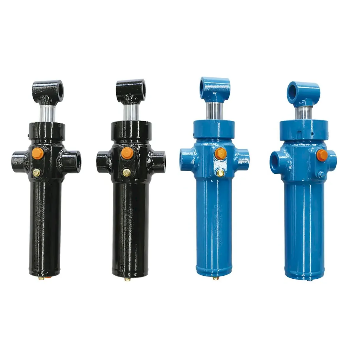
A standard rear-loading refuse compactor contains four hydraulic cylinder positions, each with a distinct engineering function and a specific failure profile that drives its specification requirements:
EJECTION
RAM
The largest lift cylinder in the vehicle — a long-stroke ram that pushes the entire compacted load from the body at the tip site. Typically a single-acting telescopic or long-stroke double-acting lift cylinder with bore 150–250 mm and stroke 3–6 m depending on body length. Used once per body-load (1–4 times per shift) but at maximum system pressure — the highest structural demand in the vehicle hydraulic system.
PACKING
BLADE
Two double-acting lift cylinders that drive the packing blade through its compaction arc — sweeping collected waste from the hopper into the body and compressing it against the ejection plate. The highest cycle frequency of any position — 600–800 complete cycles per shift in a busy urban collection route. These lift cylinders experience the most severe contamination exposure from leachate and organic waste spray.
TAILGATE
ロック
Two or four small double-acting lift cylinders that engage the tailgate locking hooks and hold the tailgate sealed against the body during compaction and transit. Low cycle frequency (locked at route start, unlocked at tip site) but must hold against the full ejection ram pressure acting on the tailgate seal — typically 20–28 MPa on the locking mechanism. Interlock circuits prevent ejection ram operation unless all tailgate locks are confirmed engaged.
BODY
TIPPING
On tipping-body compactors, additional lift cylinders raise the entire body to 50–60° for gravity-assisted discharge. Large bore (150–200 mm), medium stroke (1 500–2 500 mm), single-acting or double-acting depending on whether controlled lowering is required. Similar specification to tipper truck body lift cylinders — the primary additional requirement is that the cylinder must operate with a body full of compacted waste, typically 8–15 tonnes.
セクション02
Ejection Ram — Force, Stroke and Pressure Requirements
The ejection ram is the defining structural component of the rear-discharge compactor. Its bore must generate sufficient force to push a full compacted body load — which, after compression, can present a significant friction resistance in addition to the dead weight of the waste mass — through the body and over the tailgate lip at the tip site.
FORCE CALCULATION
The ejection force required depends on body length, compaction ratio, and the coefficient of friction between the compacted waste and the body liner. A 6 m body carrying 10 tonnes of compacted general waste at 3:1 compaction ratio requires a net ejection force of approximately 150–200 kN — driven by the friction of the compressed mass against the body sides and floor rather than its weight alone. This demands a bore of at least 150–180 mm at 20 MPa system pressure. Wet or sticky waste (commercial kitchen waste, market refuse) can require 2–3× this force.
TELESCOPIC vs LONG-STROKE
The choice between a telescopic and a long-stroke single-rod ejection ram is primarily determined by the installed height constraint beneath the body floor. A telescopic lift cylinder collapses to approximately 30% of its extended length — a 5 m stroke telescopic ram collapses to approximately 1.5 m — fitting within standard floor cross-member spacing. A long-stroke single-rod lift cylinder at the same stroke requires a collapsed length of approximately 2.8 m, which typically cannot fit within the floor structure without a dedicated tunnel or recess.
Safety interlock requirement: The ejection ram must be interlocked with the tailgate locking lift cylinders — the ejection ram must not be able to operate unless all tailgate lock cylinders are in the confirmed-locked position, verified by limit switches or proximity sensors. Operating the ejection ram with an unlocked tailgate can cause catastrophic tailgate ejection at high velocity. This interlock must be verified during commissioning and at each periodic inspection.
セクション03
Packing Blade Lift Cylinders — High-Cycle Specification
The packing blade lift cylinder operates in the worst contamination environment of any vehicle hydraulic position. The hopper environment exposes the rod to: organic leachate (acidic, pH 4–6), broken glass fragments, grit and silica from street waste, food waste oils and fats, and the physical impact of hard objects dropped from refuse collection bins. A standard lift cylinder rod seal specification will typically fail within 4–8 weeks in this environment.
ロッド保護
Hard chrome minimum 35–45 μm — heavier than standard industrial specification to provide additional wear reserve against abrasive grit. HVOF tungsten carbide coating (200–250 μm) doubles or triples rod life in glass-rich municipal waste applications and is the correct specification for high-population-density urban routes where glass contamination is constant.
WIPER SPECIFICATION
Polymer-only wipers are inadequate for the packing blade position — broken glass shards and grit pass straight through a rubber wiper lip and reach the rod seal. A two-stage wiper system with a metal scraper (steel or brass scraper ring) followed by a polyurethane dust wiper is the minimum specification. The metal scraper removes solid contamination before it can abrade the lift cylinder rod seal.
SEAL CHEMISTRY
Standard NBR seals swell and degrade rapidly in contact with organic acids and food waste oils. Polyurethane (PU 90 Shore A) rod seals provide superior chemical resistance to the pH 4–6 leachate environment typical of household refuse compaction. For industrial or food waste compactors handling cooking fats and animal waste, FKM seals offer the best chemical resistance at higher cost.
その リフトシリンダー range for refuse compactor packing blade positions is available with HVOF rod coating, metal-scraper wiper, and PU seal kit as a standard heavy-duty configuration — specify “refuse duty” at enquiry to ensure the correct seal and rod combination is built into the production unit.
第4節
Tailgate and Tipping Lift Cylinders
Tailgate cylinders and body tipping cylinders are the lowest-cycle positions in the refuse compactor hydraulic system — but they operate under specific loading conditions that make specification errors particularly consequential:
| 位置 | タイプ | BORE | プレッシャー | CRITICAL SPEC |
|---|---|---|---|---|
| Tailgate lock (hook) | Double-acting | 50–80 mm | 20–28 MPa | Load-hold under ejection ram pressure; limit switch integration; position feedback |
| Tailgate lift (open/close) | Double-acting | 80–120 mm | 16~20 MPa | Counterbalance valve — tailgate weight on fully extended lift cylinder creates buckling risk on closure |
| Body tipping (tipping compactor) | Single or double-acting | 150–200 mm | 18–25 MPa | HVOF rod (waste spray); 4:1 safety factor structural certification; mobile machinery hydraulic cylinder spec |
The tailgate lift cylinder (that swings the tailgate open and closed at the tip site) presents a specific engineering challenge: when the tailgate is fully open and the lift cylinder is at maximum extension, the tailgate’s own weight creates a compressive side load on the cylinder rod through the pivot geometry. This can cause rod buckling if the rod-to-bore ratio is not sized for the combined axial and lateral loading — specify a rod diameter of at least 65% of bore diameter for tailgate lift cylinder positions. For mobile machinery lift cylinder configurations with tipping body certification, the mobile machinery hydraulic cylinder range provides pre-certified tipping configurations.
第5節
Seal and Rod Specification for Waste Environments
The refuse environment presents a combination of chemical and mechanical seal challenges that no standard industrial seal specification is designed to handle simultaneously. The correct specification requires choosing each seal layer for its specific function in the contamination hierarchy:
LAYERED SEAL SYSTEM — PACKING BLADE LIFT CYLINDER SPECIFICATION
LAYER 1
OUTER
Steel scraper ring. Removes glass shards, grit, wire, and solid contamination from the rod surface before it can reach the rubber sealing elements. Must be steel (not brass) for glass-rich waste streams — brass scrapers are too soft and allow glass to pass through. Positioned outermost in the gland, directly exposed to the hopper environment.
LAYER 2
DUST WIPER
Polyurethane dust wiper. Captures fine grit and dust that passes the metal scraper. PU is preferred over NBR in this position because it resists the organic acids in leachate better than rubber — a swollen NBR wiper loses its scraping contact pressure rapidly. Shore A 85–88 for adequate lip force without excessive drag on the high-cycle packing blade lift cylinder.
LAYER 3
ロッドシール
PU 90–92 Shore A rod seal. Primary pressure-retaining seal. Polyurethane at this Shore A hardness provides the best combination of chemical resistance to organic acids, wear resistance under high-cycle loading, and extrusion resistance at 20–25 MPa. For food waste compactors or biogas plant waste, FKM (Viton) provides superior resistance to animal fats and cooking oils that degrade PU over time.
LAYER 4
BACKUP
PTFE backup ring. Behind the rod seal, a PTFE backup ring prevents elastomer extrusion into the diametric clearance at high pressure. PTFE is chemically inert to all the acids and fats encountered in the refuse environment and does not contribute significantly to drag at the packing blade’s normal operating speed.
第6条
Service Schedule for Refuse Vehicle Hydraulic Cylinders
Refuse vehicle lift cylinder maintenance must be planned at much shorter intervals than standard mobile equipment — the combination of contamination and high cycle rates accelerates seal wear to the point where a standard annual service interval is completely inadequate for the packing blade position:
DAILY
Before first collection: visually inspect all packing blade lift cylinder rod surfaces for oil weeping — any oil visible on the rod at the gland entry at the start of shift indicates the rod seal is failing and should be replaced that day. Wipe all exposed rod surfaces with a clean cloth. Check hydraulic reservoir level — low level after a single day’s operation indicates a circuit leak that must be found immediately.
WEEKLY
Power wash the hopper and packing blade with fleet wash — remove compacted waste residue from all lift cylinder rod surfaces and gland areas. Inspect metal scraper rings for deformation or glass fragment embedding. Check all hydraulic connections in the hopper area for weeping from connection vibration. Replace the hydraulic oil filter element every 4 weeks on high-route-density vehicles.
四半期
Full packing blade lift cylinder seal kit replacement — rod seal, dust wiper, metal scraper ring, and piston seal — as a scheduled preventive action regardless of visible leakage. Hydraulic oil sample for ISO cleanliness and water content analysis. Ejection ram rod surface inspection with eddy-current gauge — chrome below 20 μm triggers re-chroming at next annual service. Tailgate lock cylinder function test under load.
年間
Full ejection ram seal replacement and rod chrome thickness measurement. Remove ejection ram for rod re-chroming if chrome is below 20 μm at any measurement point. Replace hydraulic oil — 12 months of refuse vehicle service typically degrades oil to ISO class 19/17/14 or worse from contamination ingress. Full tailgate lift cylinder and lock cylinder inspection with pressure test at 1.5× working pressure.
応募に関するよくある質問
Refuse Compactor Cylinder Questions
Q01
Our packing blade lift cylinders are leaking at the rod seal after only 6 weeks — what is the root cause?
Six-week rod seal failure on a packing blade lift cylinder is not a seal quality problem — it is a contamination management problem. The seal is being destroyed by glass fragments, grit, or biological acids before it can reach its rated service life. The diagnostic sequence is: inspect the failed seal under magnification for the characteristic cut marks of glass penetration (sharp angular cuts across the lip), abrasive circumferential scoring (silica grit), or swelling and discolouration (chemical attack from leachate). If glass cuts are present, upgrade the outer wiper to a steel scraper ring. If abrasive scoring, improve the metal scraper contact pressure. If chemical swelling, switch from NBR to PU or FKM seal chemistry. Additionally, verify that the hopper is being power-washed at least once per week — dried organic residue accumulating around the gland entry acts as an abrasive paste that destroys any wiper specification.
Q02
The ejection ram on our compactor is slower than it used to be and requires multiple pressure relief valve activations to complete the ejection stroke — what is failing?
Slow ejection with repeated relief valve activation indicates that the ejection force required has increased beyond what the system can deliver at the set relief valve pressure. This has two common causes. The first is piston seal bypass in the ejection ram — the piston seal is worn and allows oil to bypass from the cap-end to the rod-end rather than moving the piston, so the pump is working but not moving the load. Confirm by performing a static load test: apply full pressure to the ram against a fixed stop, close the supply valve, and measure pressure decay — more than 2% drop per minute indicates piston seal bypass. The second cause is increased compaction resistance from a change in waste type — wet or commercial kitchen waste compacts at significantly higher friction than standard household waste. If the waste type has changed, the ejection ram bore may be undersized for the new load — contact the vehicle OEM or a specialist hydraulic engineer to verify the ram specification against current operational loads.
Q03
Is it acceptable to use a standard agricultural or industrial lift cylinder as a replacement for the packing blade cylinder on a refuse vehicle?
Only if the replacement matches the bore, stroke, port, and mounting specification of the original and incorporates the same heavy-duty seal and wiper specification. A standard agricultural or industrial lift cylinder with NBR seals and a polymer-only wiper will fail within weeks in the hopper environment. The bore, stroke, and mounting dimensions may be correct, but the seal and rod protection specification must be upgraded to refuse-duty grade before installation. If sourcing a replacement, specify the application explicitly as refuse compactor packing blade duty — the manufacturer must build in PU or FKM seals, a metal scraper outer wiper, and HVOF or heavy chrome rod coating. Installing a standard cylinder and expecting it to match the service life of a purpose-specified refuse-duty lift cylinder is the most common cause of unnecessarily short replacement intervals in municipal fleet management.
Q04
What hydraulic oil specification should be used in a refuse compactor that operates year-round including in cold winter conditions?
For a refuse vehicle operating in temperate climates with winter temperatures occasionally below 0°C, a high-viscosity-index (HVI) hydraulic oil such as ISO 46 HV is the correct specification — it remains pumpable at cold morning starts while maintaining adequate film strength at the elevated operating temperatures generated by continuous packing blade cycling during the afternoon portion of a collection shift. A standard ISO 46 mineral oil without the HV modifier works adequately in temperate conditions but becomes sluggish at cold start below −5°C, which stresses the hydraulic pump and causes erratic packing blade lift cylinder speed until the oil warms. For vehicles operating in climates with sustained temperatures below −15°C, ISO 32 HV or a dedicated arctic-grade hydraulic oil is required. Change the oil annually in a refuse vehicle regardless of the hours or kilometres operated — the combination of contamination ingress from the hopper environment and thermal degradation from continuous cycling makes the standard hours-based change interval an inadequate proxy for actual oil condition in this application.
REFUSE COMPACTOR LIFT CYLINDER SPECIFICATION
Sourcing Lift Cylinders for Refuse or Waste Equipment?
Our application team specifies refuse-duty リフトシリンダー with the correct seal chemistry, rod coating, and wiper specification for ejection ram, packing blade, tailgate, and tipping body positions — matched to your vehicle model and collection route duty.
編集者: Cxm














