
TECHNICAL GUIDE · CUSHIONING DESIGN · HYDRAULIC LIFT CYLINDERS
Cilindro idraulico
Cushioning Design
End-of-Stroke · Deceleration · Pressure Spike
When a hydraulic lift cylinder reaches end-of-stroke at operating speed, the kinetic energy of the moving mass must be absorbed somewhere. Without a cushioning mechanism, that energy transfers instantaneously into a pressure spike in the trapped oil column — a spike that can reach 3–10 times normal working pressure in milliseconds and stress every structural component between the piston and the end-cap. End-of-stroke cushioning in a lift cylinder converts this destructive kinetic energy into a controlled deceleration, protecting weld seams, end-cap threads, and the machine structure. This guide covers lift cylinder cushion design principles, sizing calculations, adjustable versus fixed configurations, and failure modes from incorrect specification.
Adjustable Cushion
Pressure Spike
LIFT CYLINDERS · CUSHIONING ENGINEERING · JULY 2026
REFERENCE · CUSHIONING KEY PARAMETERS
UNCUSHIONED SPIKE
3–10× WP
End-of-stroke pressure spike without cushioning — sufficient to crack end-cap welds or fracture port threads on repeated impacts
CUSHION LENGTH
20–80 mm
Typical cushion engagement length — longer cushions provide gentler deceleration at high speed or heavy load
CUSHION PRESSURE
1.5–3× WP
Target peak cushion pressure during deceleration — exceeding 3× working pressure indicates under-specified cushion length or area
CHECK VALVE
Free start-out
Integral check valve in cushion circuit bypasses the needle on extension start-out — prevents slow start and seal squeeze on reversed stroke
SEZIONE 01
Why Cushioning Is Required — The Physics of End-of-Stroke
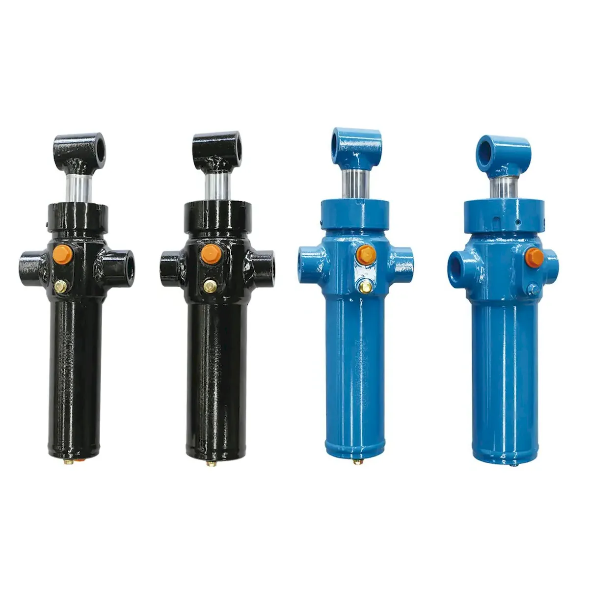
The kinetic energy of a moving lift cylinder load at end-of-stroke is given by E = ½mv². For a 2 000 kg load moving at 0.5 m/s — a moderate speed for an industrial lift cylinder — the kinetic energy at end-of-stroke is 250 J. Without cushioning, this energy must be absorbed by the oil column trapped between the piston and the end-cap as the directional valve closes. The result is a pressure spike whose magnitude depends on the stiffness of the trapped oil volume:
WITHOUT
CUSHION
The piston strikes the end-cap mechanically. Depending on oil compressibility and response time of the pressure relief valve, the impact load can reach 3–10× working pressure for a 2–5 ms spike. This spike is transmitted through the end-cap welds, barrel, and all port connections simultaneously. On a high-cycle machine, each uncushioned impact is a fatigue event — weld crack propagation, port thread fatigue, and end-cap deformation accumulate with each cycle until visible failure occurs, often thousands of cycles before the seal or rod would otherwise need attention.
WITH
CUSHION
The cushion converts kinetic energy into a controlled hydraulic back-pressure over the cushion engagement length. The deceleration force acts in the direction opposing motion — decelerating the piston and load to near-zero velocity before mechanical contact with the end-cap. Peak cushion pressure is typically 1.5–3× working pressure, sustained over 20–80 mm of travel rather than delivered as a 2 ms spike. The cumulative fatigue damage to the lift cylinder structure is reduced by one to three orders of magnitude compared to uncushioned operation.
SEZIONE 02
Fixed Cushion Design — Geometry and Sizing
A fixed cushion built into a lift cylinder is formed by a spigot on the piston (or on a separate sleeve) that enters a matching bore in the end-cap during the last portion of the stroke. The annular clearance between the spigot and the bore determines the flow restriction — a smaller clearance generates a higher back-pressure for a given velocity. Fixed cushions cannot be adjusted in service and must be correctly sized at the design stage for the actual operating speed and load:
SPIGOT CLEARANCE
The diametric clearance between the cushion spigot and bore is the primary flow control parameter. Typical values: 0.05–0.20 mm diametric clearance for standard industrial speeds. Too small: excessive back-pressure, risk of hydraulic lock. Too large: insufficient deceleration, piston still impacts end-cap at reduced speed. The clearance is specified at the cushion bore diameter — a 50 mm spigot in a 50.10 mm bore has 0.10 mm diametric clearance.
CUSHION LENGTH
Longer cushion engagement means a lower peak pressure for the same kinetic energy absorption. Standard cushion lengths: 20–30 mm for low-speed, light-load cylinders; 40–60 mm for medium-duty industrial lift cylinders; 60–80 mm for high-speed or heavy-load applications. The cushion length is determined by the deceleration distance needed to reduce the load from entry velocity to near-zero without exceeding the allowable peak pressure.
CHECK VALVE
Every fixed-cushion lift cylinder must include an integral check valve that bypasses the cushion restriction during the reversed stroke start-out. Without the check valve, the piston would have to accelerate from rest through the full cushion restriction — resulting in very slow initial movement and potential seal damage from differential pressure across the gland before the piston has moved. The check valve opens on reversed stroke, filling the cushion pocket rapidly with oil and allowing free start-out acceleration.
SEZIONE 03
Adjustable Cushion — Needle Valve and Setting Procedure
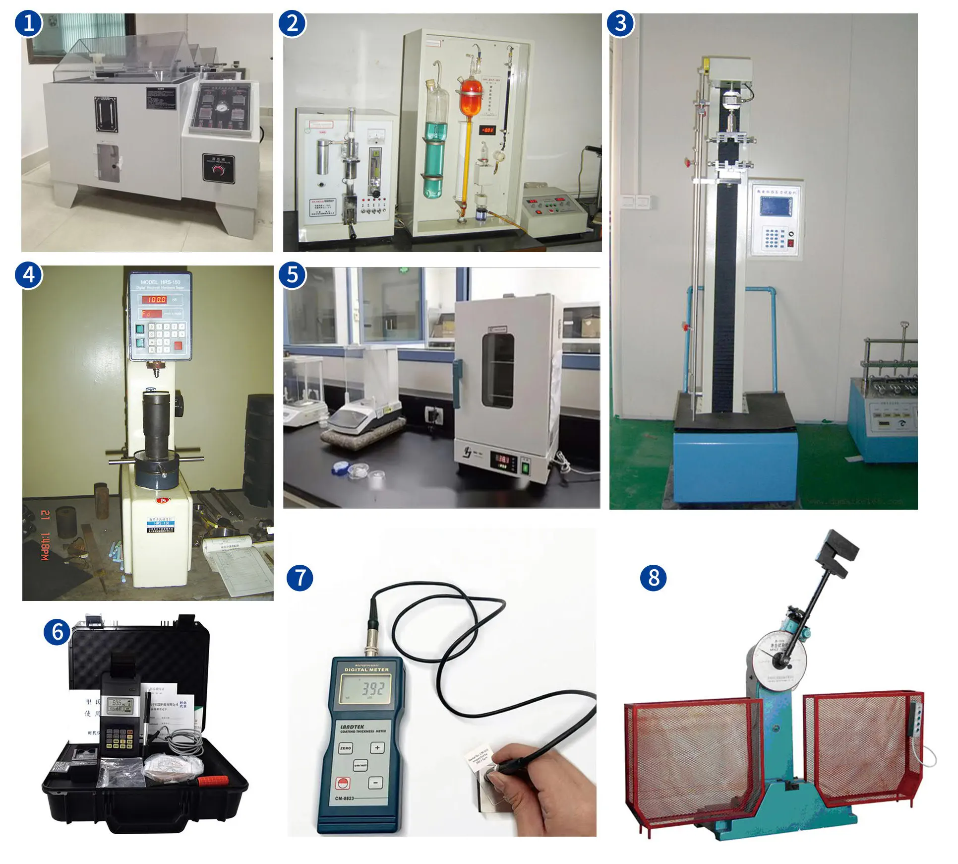
An adjustable cushion adds a needle valve to the fixed-cushion geometry, allowing the flow restriction — and therefore the deceleration force — to be tuned in service. This is the preferred configuration for lift cylinders whose operating speed or load may vary over the machine’s working life:
STEP 1
Set the needle fully open. Before first operation, open the adjustable cushion needle valve completely — fully counter-clockwise on most designs — to ensure no restriction on the initial test cycles. Never start a new lift cylinder installation with an unknown needle valve position.
STEP 2
Operate at design speed and load. Run the lift cylinder through several complete cycles at the intended operating speed with the full design load applied. Listen and feel for end-of-stroke impact — a mechanical knock at end of travel indicates the piston is still contacting the end-cap at speed.
STEP 3
Close the needle by quarter-turns. Turn the needle valve clockwise by one quarter-turn. Operate 3–5 full cycles. If the knock persists, close another quarter-turn and repeat. Continue until the lift cylinder arrives at end-of-stroke smoothly without audible impact. This is the correct setting.
STEP 4
Verify and lock. Measure the cycle time — closing the needle further than the minimum required for smooth arrival increases cycle time unnecessarily. Once the optimal setting is confirmed, tighten the locknut on the needle valve to prevent vibration from altering the setting during operation. Mark the correct needle position on the end-cap with a permanent marker as a reference for future maintenance.
CAUTION
Do not over-close the needle. A needle valve closed too far creates excessive back-pressure in the cushion pocket — the piston decelerates too hard, extending cycle time and potentially causing the piston seal to be loaded against the bore from lateral pressure at end-of-stroke. The correct cushion setting produces a smooth, audibly quiet arrival — not the slowest possible arrival.
SEZIONE 04
Cushion Sizing Calculation — Worked Example
The cushion for a lift cylinder is sized to decelerate the moving mass from entry velocity to zero within the cushion length, without the back-pressure exceeding the allowable maximum (typically 1.5–2× working pressure). A simple energy-balance approach gives the required cushion length:
WORKED EXAMPLE — 1 500 kg LOAD, 0.4 m/s, 100 mm BORE, 20 MPa SYSTEM PRESSURE
①
Kinetic energy at cushion entry: E = ½ × 1500 × 0.4² = 120 J
②
Allowable cushion peak pressure: 1.8 × 20 = 36 MPa
③
Cushion bore area (annular, spigot Ø 70 mm in Ø 100 mm bore): A = π/4 × (0.10² − 0.07²) = 4.00 × 10⁻³ m²
④
Deceleration force available: F = P × A = 36 × 10⁶ × 4.00 × 10⁻³ = 144 000 N
⑤
Required cushion length: L = E / F = 120 / 144 000 = 0.00083 m = 0.83 mm
⑥
Design cushion length with 30× safety factor: 0.83 × 30 = 25 mm — select standard 30 mm cushion. The large safety factor accounts for non-uniform pressure distribution during deceleration and the assumption of constant peak pressure which over-estimates efficiency. In practice, 25–40 mm is adequate for this duty.
For lift cylinders where operating speed or load varies, specify an adjustable cushion rather than attempting to calculate the fixed clearance for a range of conditions. All standard cilindri di sollevamento in the product range are available with fixed or adjustable cushion options on both cap-end and rod-end. Specify “cushion both ends,” “cap-end cushion only,” or “rod-end cushion only” according to the application’s stroke direction and load profile.
SEZIONE 05
Applications Requiring Cushioning — Which Lift Cylinders Need It
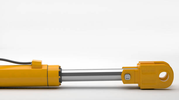
Cushioning is not universally required — a slow-moving, lightly loaded lift cylinder may never need it. The decision depends on the product of mass and velocity squared (kinetic energy) and the number of end-of-stroke events per year:
| APPLICAZIONE | SPEED | CYCLES/YEAR | CUSHION? | TIPO |
|---|---|---|---|---|
| Agricultural tractor rear lift | 0.05–0.10 m/s | 500–2 000 | Opzionale | Low speed — fixed cushion adds margin for draft control valve overlap |
| Industrial press feed cylinder | 0.3–0.6 m/s | 50 000–200 000 | Required | Adjustable — speed varies with material and tooling change |
| Aerial work platform boom | 0.1–0.3 m/s | 10 000–50 000 | Required | Fixed — EN 280 requires smooth end-of-stroke for personnel safety |
| Dump truck body hoist | 0.05–0.15 m/s | 5 000–15 000 | Required | Fixed — body weight creates high impact energy despite low speed |
| Concrete pump boom arm | 0.2–0.5 m/s | 5 000–20 000 | Mandatory | Adjustable — pressure pulse from concrete pumping adds to end-of-stroke load |
For high-cycle industrial lift cylinder applications requiring cushioning confirmation, the cilindro idraulico per ingegneria industriale range is available with fixed or adjustable cushions at both ends. Provide the operating speed, load, bore, and annual cycle count when enquiring — our engineering team will confirm the appropriate cushion configuration.
SEZIONE 06
Cushion Failure Modes and Diagnostic Signs
Cushioning failure in a lift cylinder manifests through recognisable diagnostic symptoms that allow the failure mode to be identified before structural damage becomes irreversible:
HYDRAULIC
KNOCK
Symptom: Sharp metal-on-metal knock at end-of-stroke on a lift cylinder that previously operated silently. Cause: Cushion needle valve has vibrated open, cushion check valve has stuck open (bypassing the needle), cushion spigot has worn and clearance enlarged beyond specification, or contamination has blocked the check valve seat open. Action: Re-set the needle valve if accessible; if the knock persists with needle fully closed, the check valve or spigot requires inspection and likely replacement.
SLOW
START-OUT
Symptom: Lift cylinder accelerates very slowly from end position before reaching normal speed — particularly noticeable on the return stroke from cushioned end. Cause: Cushion check valve is not opening properly on reversed stroke — the oil filling the cushion pocket must pass through the restricted needle path rather than through the free-flow check valve path. Check valve may be stuck, seat debris, or spring broken. Action: Remove and inspect the check valve; replace the check valve cartridge.
VERY SLOW
END APPROACH
Symptom: Lift cylinder decelerates dramatically as it approaches end-of-stroke — cycle time is far longer than specified and the load appears to barely move in the last portion of travel. Cause: Adjustable cushion needle valve is over-closed — the flow restriction is so high that the oil can barely escape the cushion pocket. Common after maintenance by personnel who closed the needle “to be safe” without following the quarter-turn adjustment procedure. Action: Re-set the needle valve following the STEP 1–4 procedure in Section 03 of this guide.
END-CAP
WELD CRACK
Symptom: Oil seepage from the end-cap weld seam, particularly from the weld toe — the junction between the barrel tube and the end-cap face. May be accompanied by rust staining or external crack visible under the coating. Cause: Long-term fatigue crack growth driven by repeated uncushioned end-of-stroke pressure spikes. Each spike cycles the lift cylinder weld between high tension and return — classical high-cycle fatigue in the heat-affected zone of the weld. Action: The lift cylinder must be removed from service immediately. The weld crack will propagate to full barrel failure under continued operating pressure. A new lift cylinder with correctly specified end-of-stroke cushioning should replace the failed unit — the root cause (inadequate cushioning) must be corrected, not just the failed component.
TECHNICAL FAQ
Cushioning Design Questions
Q 01
Can cushioning be added to an existing lift cylinder that was built without it?
Adding cushioning to an existing lift cylinder that was built without it is possible but requires full disassembly and machining of new end-caps with cushion bores, and a new piston or piston sleeve with the cushion spigot geometry. In most cases, this rebuild cost is comparable to purchasing a new lift cylinder with cushions built in from manufacture — particularly for small-bore cylinders where the machining cost is a high fraction of the total component cost. The exception is large-bore, long-stroke cylinders where the barrel and rod represent the majority of the value — in these cases, retrofitting cushion end-caps can be cost-effective if the bore and rod are in serviceable condition. A more practical approach for existing uncushioned lift cylinders is to reduce the operating speed via flow control valves so that the kinetic energy at end-of-stroke falls below the threshold that causes structural fatigue. This is a valid interim measure but reduces cycle time — the correct long-term solution is a replacement lift cylinder with cushions built in from new manufacture.
Q 02
Our lift cylinder has cushions on both ends but still makes a knock at the extension end-of-stroke only. Retraction arrives smoothly. Why only one end?
The asymmetry in cushioning performance between extension and retraction end-of-stroke almost always results from a difference in piston velocity or effective mass at the two ends. In a double-acting lift cylinder, the effective annular area on the rod end is smaller than the full bore cap end — so for the same pump flow rate, the rod-end retraction speed is higher than the cap-end extension speed. If the cushions are identically sized for both ends, the retraction cushion must absorb more kinetic energy per unit time than the extension cushion, yet the cushion area available is also smaller on the rod end. A lift cylinder that arrives smoothly at cap-end extension but knocks at rod-end retraction needs a longer cushion or smaller clearance on the rod end than the cap end. Review the lift cylinder cushion specification for each end independently, using the actual piston velocity and load at that stroke direction — do not assume symmetrical cushion sizing is correct when the areas and velocities differ.
Q 03
What is the difference between a cushion and an external deceleration valve — when should each be used?
An integral cushion built into the lift cylinder end-cap and an external deceleration valve (mounted in the hydraulic circuit) both achieve the same goal — decelerating the piston before end-of-stroke — but through different mechanisms and at different points in the circuit. An integral cushion acts on the oil trapped between the piston and the end-cap face — it is always correctly positioned relative to the piston’s actual location regardless of circuit configuration. An external deceleration valve acts on the oil flowing through the circuit to the lift cylinder and is triggered by a position cam or proximity switch — it can decelerate the piston from any point in the stroke, not just the final cushion length. External deceleration valves are preferred when the deceleration zone must be longer than a practical cushion geometry allows (for example, decelerating a fast-moving overhead crane trolley over 200–300 mm), when the cylinder cannot easily accommodate a cushion spigot (very short stroke cylinders), or when the deceleration point must be adjustable without opening the cylinder. Integral cushions are preferred for standard lift cylinder duty where the deceleration requirement is modest and the stroke geometry allows a standard spigot-and-bore cushion pocket to be machined into the end-cap. Many high-performance lift cylinder systems use both — the external valve reduces velocity and the integral cushion absorbs the final residual kinetic energy at full end-of-stroke position.
Q 04
Does low temperature affect cushion performance — should we adjust the needle valve setting in winter?
Yes — hydraulic oil viscosity increases significantly as temperature drops, and this directly affects cushion performance. A lift cylinder cushion needle valve set at warm operating temperature (50–60°C, where ISO 46 oil has a viscosity of approximately 10 cSt) will produce a much higher back-pressure at cold start temperatures (0–10°C, where the same oil may be 200–400 cSt). The increased viscosity means oil exits the cushion pocket far more slowly for the same needle opening — the effective cushion restriction is several times higher in cold conditions than at operating temperature. A hydraulic lift cylinder with an adjustable cushion whose needle is set correctly at operating temperature may arrive at end-of-stroke almost hydraulically locked at cold start, severely restricting the first few cycles of the day. For machines that must operate in cold conditions from cold start, the lift cylinder cushion needle valve should be set at cold temperature rather than hot, and a high-viscosity-index (HV-grade) oil used to minimise the viscosity difference between cold and operating temperatures. Alternatively, a warm-up cycle at reduced speed should be included in the machine’s start procedure before full-speed production operation begins.
CUSHIONED LIFT CYLINDER SPECIFICATION
Need Cushioning on Your Lift Cylinder?
Tutto cilindri di sollevamento in the product range are available with fixed or adjustable cushions on cap-end, rod-end, or both — specify the operating speed, load, bore, and annual cycle count and our engineers will confirm the correct cushion configuration.
Redattore: Cxm














