
ENGINEERING GUIDE · CUSTOM & OEM DESIGN · HYDRAULIC LIFT CYLINDERS
Custom Lift Cylinder
Engineering
OEM · Special · Non-Standard
Standard catalogue products cover the majority of applications by bore, stroke, and mounting configuration — but a significant proportion of machine designs require custom or OEM lift cylinders where the installation envelope, integration requirements, or performance specification cannot be met from stock. This guide explains what drives the need for custom specification, how to communicate those requirements effectively, what the engineering process involves, and how qualification testing ensures the custom lift cylinder performs as specified before production begins.
Non-Standard Bore & Stroke
Qualification Testing
LIFT CYLINDERS · CUSTOM ENGINEERING · JULY 2026
REFERENCE · CUSTOM LIFT CYLINDER DEVELOPMENT TIMELINE
SPEZIFIKATION
1–2 weeks
Drawing review, bore/stroke calculation, seal and material selection, pricing
PROTOTYPE
4–8 weeks
First-article manufacture, dimensional inspection, pressure testing and delivery
QUALIFICATION
2–6 weeks
Customer machine installation, function testing, cycle endurance if required
SERIES PRODUCTION
2–4 weeks/batch
Locked drawing, agreed inspection protocol, recurring supply to forecast
ABSCHNITT 01
When Standard Catalogue Cylinders Are Not Enough
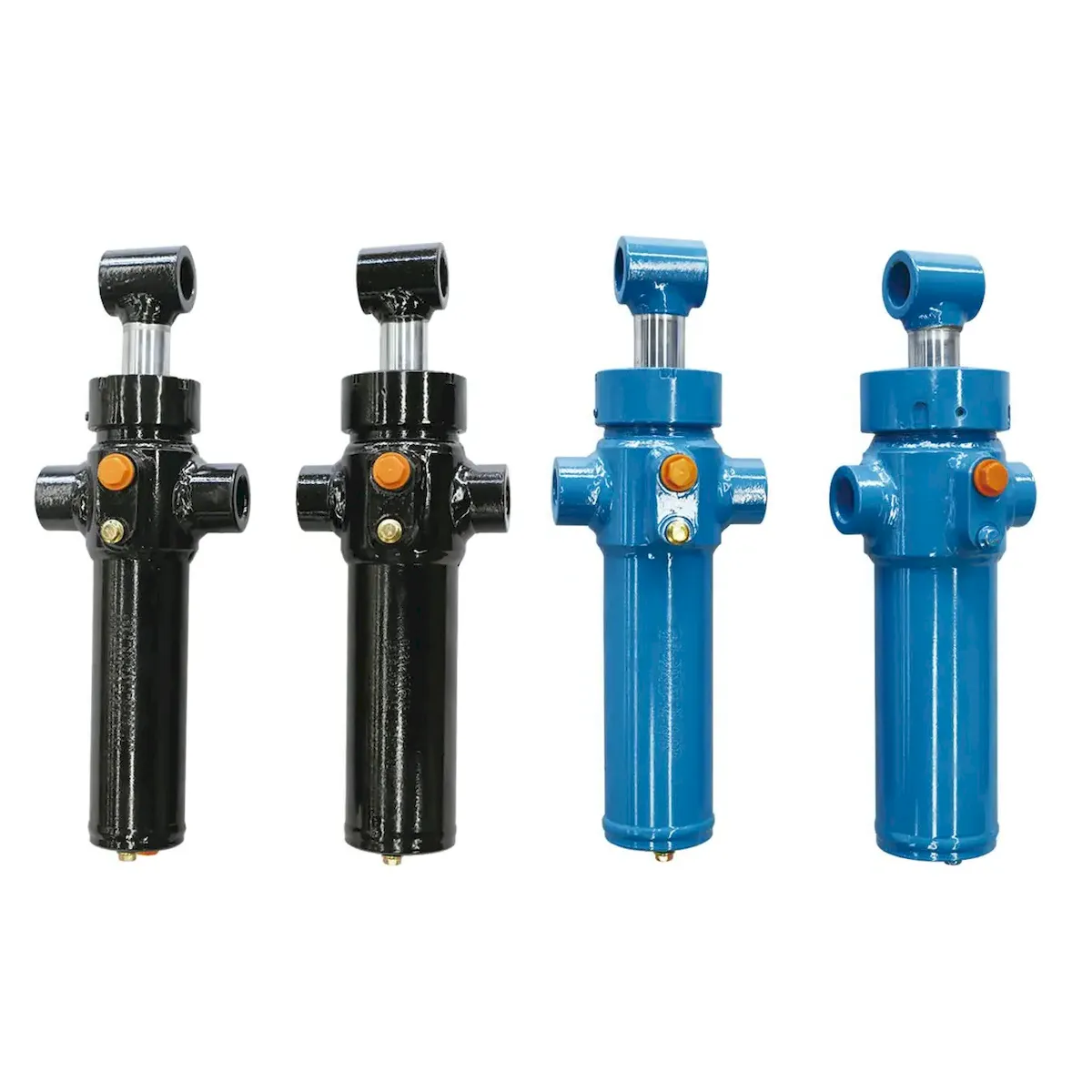
The decision to specify a custom lift cylinder rather than adapting the machine design to a standard product is driven by one of five engineering constraints. Understanding which constraint applies to your application determines how the custom specification should be written and which parameters have the most tolerance for adjustment:
ENVELOPE
Installation envelope constraint. The machine’s structural design places the lift cylinder mounting points at a fixed distance from each other — and the collapsed and extended lengths, pin diameters, or port positions of standard cylinders do not fit within those fixed constraints. This is the most common driver for custom specification in OEM machine design.
PERFORMANCE
Performance specification gap. The application requires a bore, pressure rating, or stroke that falls between two standard catalogue sizes — and the smaller standard size is marginally insufficient while the larger is wasteful of space, weight, and cost. A custom cylinder with a non-standard bore bridges the gap precisely.
INTEGRATION
Hydraulic integration requirement. The application requires a cylinder with an integrated holding valve, pilot-operated check, counterbalance valve, or position transducer that is not available as a standard catalogue feature. Building these functions into the cylinder end-cap eliminates external valve manifolds and reduces the hydraulic schematic’s connection count.
ENVIRONMENT
Environmental specification. The application demands a material, coating, or seal specification that standard cylinders do not offer — stainless steel rod for marine use, food-grade seal materials for food processing, or ATEX-rated port connections for hazardous atmosphere installations.
VOLUMEN
OEM volume economics. An OEM machine builder produces sufficient machine volume that designing a custom cylinder to match the machine’s geometry precisely — rather than adapting the machine to fit a standard cylinder — produces a cost-per-machine saving that more than justifies the tooling and qualification investment.
ABSCHNITT 02
Common Custom Lift Cylinder Configurations
Custom cylinders most commonly differ from standard products in one or more of the following six areas. Each area of customisation has a different impact on engineering complexity and lead time:
NON-STANDARD BORE
Any bore not in the standard range (e.g. 55 mm, 72 mm, 110 mm). Requires a custom honing mandrel and new seal gland dimensions. Moderate cost impact — tooling is amortised over order volume.
NON-STANDARD STROKE
Any stroke not in the standard catalogue. Relatively easy — barrel tube is cut to length and the rod machined to specification. Very common in OEM programmes.
CUSTOM MOUNTING
Non-standard pin diameter, eye width, flange bolt pattern, or trunnion position. Requires machined end-cap modification. Lead time impact: +1 week. Very common where the lift cylinder must mount to an existing machine structure with fixed pin positions.
INTEGRATED VALVES
Pilot-operated check valves, counterbalance valves, or pressure-compensated flow controls machined directly into the cylinder end-cap or port block. Eliminates external valve connections and reduces leak points. Lead time impact: +2–3 weeks. Significant engineering review required for valve setting and circuit interaction.
MULTI-STAGE TELESCOPIC
Custom stage count, stage diameters, and stage sequencing for applications where the standard telescopic configurations do not provide the right collapsed-to-extended length ratio. Stage sequencing (which stage extends first) can be specified by adjusting port positions and inter-stage passage diameters.
SENSOR INTEGRATION
Magnetostrictive position transducer, reed switch end-of-stroke detection, or pressure transducer port incorporated into the barrel or end-cap. Enables closed-loop position control without an external sensor bracket. Requires electrical connection design and EMC consideration in the broader machine design.
ABSCHNITT 03
How to Write an Effective Custom Specification
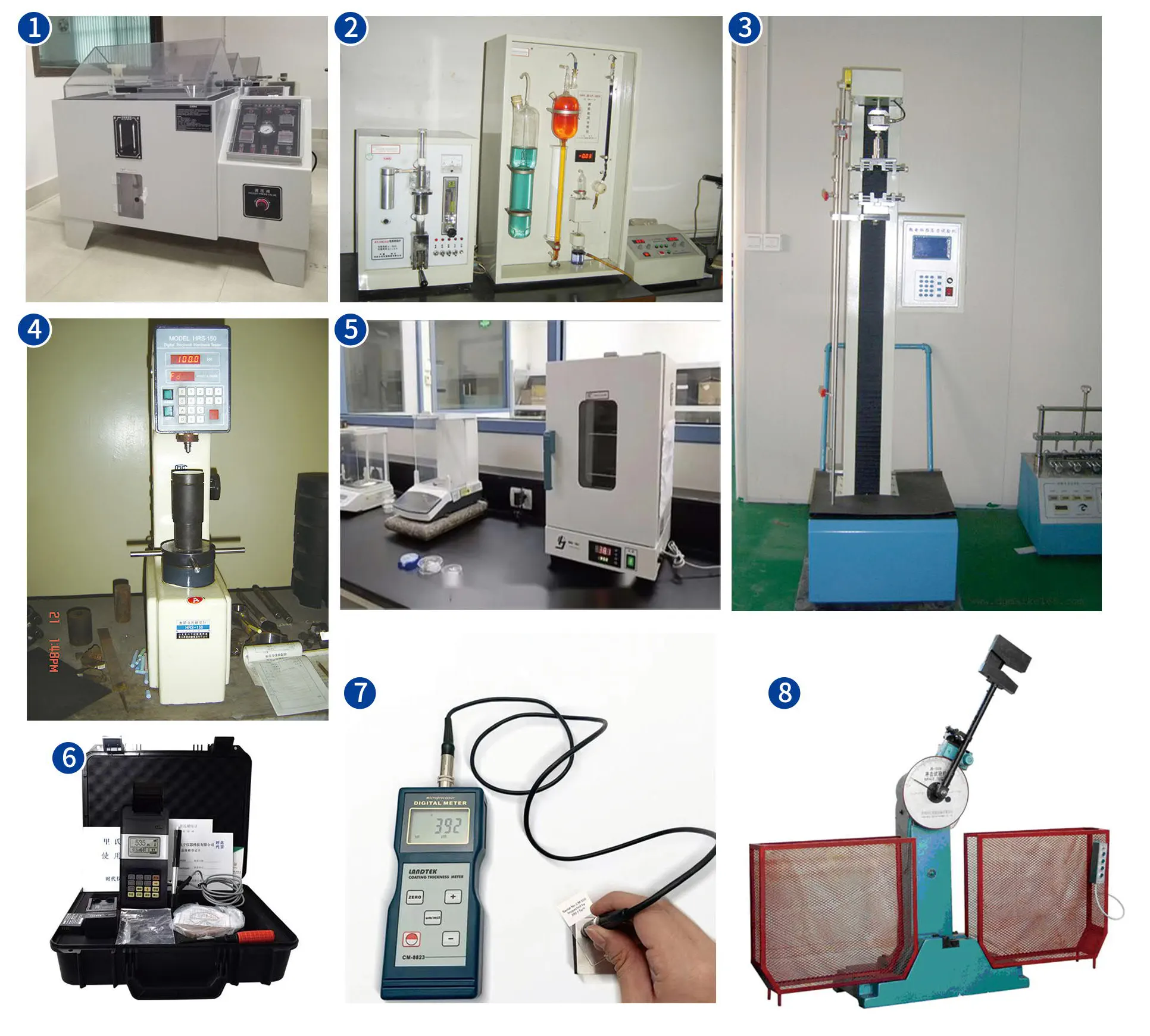
An effective custom lift cylinder specification contains twelve parameters. Omitting any of them creates ambiguity that delays the engineering process:
01
Required extension force (N or kN) — at what position in the stroke?
02
Required retraction force (if double-acting) — same question
03
System operating pressure (MPa) and maximum allowable pressure
04
Required stroke (mm) — from pin centre to pin centre or shoulder to shoulder?
05
Maximum collapsed length and maximum extended length available in the machine envelope
06
Mounting configuration: eye both ends, flange cap end, trunnion, clevis — pin diameter and width
07
Port size and type (BSPP, BSPT, SAE, metric) and port position on the cylinder body
08
Hydraulic fluid type (mineral ISO 46, HFC, phosphate-ester, biodegradable) and operating temperature range
09
External environment: indoor/outdoor, corrosion class, proximity to water or chemicals
10
Duty cycle: expected cycles per day, duty frequency, and expected annual operating hours
11
Side loads or bending moments — does the cylinder carry any non-axial forces?
12
Annual volume required and target price point — drives tooling investment decisions
Send completed specifications to our engineering team via the enquiry form with any available machine drawings. A machine drawing — even if preliminary — is more useful than a list of requirements because it shows the spatial constraints that drive the cylinder geometry, and often reveals constraints that the specification writer was not aware of.
ABSCHNITT 04
The Custom Engineering and Prototype Process
The custom lift cylinder engineering process follows a defined sequence from specification receipt to first-article delivery. Understanding this sequence helps the customer manage their programme schedule around the prototype timeline:
STAGE 1
1–3 days
Engineering Review
Specification is reviewed by an application engineer who verifies the force and pressure calculations, checks for geometric conflicts in the collapsed/extended envelope, and identifies any technical questions that must be answered before a compliant design can be produced. A detailed technical questionnaire is returned within 1–3 working days if clarification is needed.
STAGE 2
3–5 Tage
Design and Drawing
A dimensioned 2D drawing and 3D CAD model is produced. The drawing is issued to the customer for approval — the customer verifies that all dimensions, port positions, and mounting geometry fit the machine design. This is the only opportunity to change the lift cylinder geometry without incurring machining cost; changes after approval of the drawing are treated as a new revision and may restart the prototype timeline.
STAGE 3
3–5 weeks
First-Article Manufacture
The prototype is manufactured against the approved drawing. Custom tooling (honing mandrels, port thread taps, seal installation tools) is produced as required. A dimensional inspection report confirms all drawing dimensions have been achieved. It is then pressure-tested to 1.5× rated working pressure and the result documented.
STAGE 4
2–6 weeks
Customer Qualification
The prototype lift cylinder is installed in the customer’s machine. Function testing verifies that extension force, retraction force, stroke, and speed meet the specification. Endurance testing — if required by the application — runs the lift cylinder for the required cycle count before production approval is given. Any design changes identified during qualification trigger a drawing revision and a second prototype build.
STAGE 5
Ongoing
Drawing Lock and Series Production
Once qualification is complete and the drawing is approved, a controlled drawing is issued with a revision number and effective date. This drawing is the manufacturing standard for all series production lift cylinders. No manufacturing changes are made without issuing a new drawing revision and obtaining customer approval — ensuring that production cylinders always match the qualified prototype specification.
ABSCHNITT 05
Qualification Testing Requirements
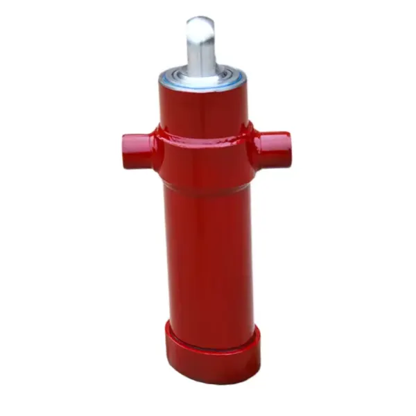
Qualification testing scope scales with the application’s safety level and cycle frequency. Not all custom lift cylinders require endurance testing — but every custom lift cylinder requires at minimum the three tests below:
HYDROSTATIC PRESSURE TEST
Mandatory for all custom lift cylinders. Apply 1.5× rated working pressure, hold for minimum 30 seconds, verify zero leakage at all seals and port connections. Test must be performed and documented on each production cylinder, not just the prototype.
DIMENSIONAL VERIFICATION
First-article inspection verifying all drawing dimensions — bore diameter, rod diameter, stroke length, collapsed length, pin diameters, port positions, and thread specifications — are within the drawing tolerances. A signed inspection report accompanies each prototype delivery.
FUNCTIONAL CYCLE TEST
Minimum 50 full-stroke cycles at rated pressure and load, verifying consistent extension and retraction force and speed. For personnel-carrying lift cylinders, the functional test includes a load-hold test at 125% rated load with the cylinder held at mid-stroke for minimum 10 minutes.
For high-cycle OEM applications, an additional endurance test is recommended — typically 10% of the expected service life cycle count run on a test bench before machine installation. This identifies any seal wear rate issues while there is still time to change the specification before the full production tooling investment is committed. Contact the Hubzylinder application engineering team to define the appropriate qualification test scope for your specific application.
ABSCHNITT 06
OEM Series Supply and Drawing Control

Once a custom lift cylinder enters series production, a structured supply and drawing control framework ensures that every production unit matches the qualified prototype specification — and that changes to the specification are managed in a controlled way that protects the OEM machine builder’s product consistency:
DRAWING CONTROL
All production lift cylinders are manufactured against a revision-controlled drawing. The drawing revision number and issue date appear on every test certificate and delivery note. Any change to materials, dimensions, or manufacturing processes requires a new drawing revision, written approval from the OEM engineering team, and a new first-article inspection before the changed specification enters production.
BATCH CERTIFICATION
Each production batch of custom lift cylinders is supplied with a batch certificate recording: the drawing revision against which the batch was manufactured; the pressure test results for each cylinder in the batch (pass/fail at 1.5× rated pressure); the material traceability reference for the barrel, rod, and seal materials; and the batch quantity and serial number range.
FORECAST SUPPLY
Custom lift cylinder production lead time can be reduced significantly for OEM programmes with predictable volume by providing a rolling 3-month production forecast. This allows raw material to be pre-purchased and blank machining to begin in advance of firm orders — reducing the effective lead time from the full 4-week manufacturing cycle to 1–2 weeks for forecast volumes. The Hydraulikzylinder im Industriebau range supports OEM volume programmes with dedicated production slots for regular customers.
Häufig gestellte Fragen zur Anwendung
Custom Cylinder Engineering Questions
Frage 01
What is the minimum order quantity for a custom lift cylinder?
There is no fixed minimum order quantity for a custom lift cylinder, but the economics of custom production change significantly with volume. For prototypes and low-volume specialised applications (1–10 units per year), the custom tooling and engineering costs are amortised across a small quantity, making the unit price significantly higher than a standard catalogue cylinder of equivalent specification. For OEM volumes of 50–200 units per year, the tooling investment is typically recovered within the first year and unit costs approach standard catalogue pricing at the equivalent specification. Below about 5 units total lifetime volume, the customer should seriously evaluate whether the machine design can be adapted to fit a standard catalogue lift cylinder before committing to a custom programme — in most cases, a machine design modification is more cost-effective than a custom cylinder at very low quantities.
Frage 02
Can I have a custom lift cylinder with both a non-standard bore and an integrated counterbalance valve?
Yes — custom lift cylinders can combine multiple non-standard features in a single design. The engineering sequence is: agree on bore and stroke from force and envelope requirements, then mounting configuration, then integrated valve functions. Integrating a counterbalance valve into a non-standard bore lift cylinder requires that the valve’s flow capacity is correctly matched to the cylinder bore and the expected flow rate at the target extension and retraction speed. An undersized counterbalance valve orifice will restrict flow and slow the lift cylinder; an oversized valve may not provide adequate back-pressure for load stability. The application engineer will calculate the required valve Cv specification as part of the custom design review, and the valve setting will be verified during the functional cycle test on the prototype.
Frage 03
How do I protect my custom lift cylinder design from being copied or supplied to a competitor?
Custom lift cylinder designs can be protected through a combination of commercial and legal mechanisms. The most effective commercial protection is a supply agreement that designates the specific lift cylinder drawing as proprietary to the OEM customer — meaning it will not be supplied to any third party without the customer’s written consent. This agreement should be established before the design process begins, not after the prototype is complete. The customer retains ownership of any drawings or specifications they provide; the manufacturer’s engineering input — where it is original design work beyond adapting the customer’s concept — may be subject to negotiation, and this intellectual property allocation should be explicitly agreed in writing. For lift cylinder designs with genuinely novel features, patent protection may be appropriate; consult an intellectual property attorney to assess whether the specific design features are patentable in the relevant markets before disclosing them without a non-disclosure agreement in place.
Frage 04
What information do I need to provide for a custom telescopic lift cylinder design?
Custom telescopic lift cylinder specifications require the twelve standard parameters (Section 3) plus four additional items specific to telescopic design: the required collapsed length (the maximum body length when all stages are fully retracted), the required extended length (the minimum distance from the body base to the tip of the fully extended innermost stage), the preferred number of stages (which is driven by the ratio of collapsed to extended length — a 5:1 ratio typically requires a 4-stage telescope), and the required stage sequencing if specific extension order matters for the application. For a tipper truck front-top configuration, also provide the body length, A-frame height, and target tip angle so that the stroke can be calculated from first principles rather than estimated. A preliminary machine envelope drawing — even a hand sketch with key dimensions — is the single most useful input for a telescopic custom design enquiry.
CUSTOM LIFT CYLINDER ENGINEERING
Ready to Start a Custom Lift Cylinder Project?
Send us your machine drawing and performance requirements — our engineering team will return a specification, dimensional sketch, and quotation within 5 working days. Standard and custom lift cylinders are available from the full Hubzylinder product range.
Herausgeber: Cxm














