
SELECTION GUIDE · DUMP TRUCK HYDRAULICS · TELESCOPIC LIFT CYLINDERS
Telescopic Lift Cylinders
for Dump Trucks
选材指南
Telescopic lift cylinders are the defining hydraulic component of every dump truck — their ability to deliver a long extension stroke from a compact collapsed length is the engineering solution that makes body tipping possible within a chassis envelope that a conventional single-stage cylinder simply cannot fit. This guide covers the complete selection framework: single-acting vs double-acting, stage count, front-mount vs underbody configuration, pressure sizing, and maintenance.
2–5 Stage Selection
Front Mount · Underbody
LIFT CYLINDERS · DUMP TRUCK APPLICATION ENGINEERING · JULY 2026
SYSTEM REFERENCE · DUMP TRUCK TELESCOPIC LIFT CYLINDER PARAMETERS
STAGE COUNT
2–5
Nested stages — collapsed length is 20–40% of full extended stroke
STROKE RANGE
1 500–8 000 mm
Extended stroke length — determines body tipping angle at given hinge geometry
系统压力
14–21兆帕
Working pressure — varies by body payload and stage count
OUTER BORE
100–360 mm
First-stage barrel diameter — determines maximum lift force at rated pressure
第 01 节
Why Dump Trucks Need Telescopic Lift Cylinders
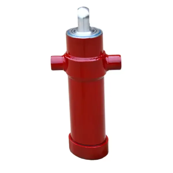
A dump truck body must tip to approximately 45–60 degrees to discharge its payload cleanly. At a typical hinge-to-cylinder mounting geometry, achieving 60 degrees of tip angle requires a cylinder stroke of 2 000–4 500 mm depending on the body length. A conventional single-stage rod cylinder of 3 000 mm stroke has a collapsed length of roughly 3 300 mm — far too long to fit between the chassis frame and the dump body at rest.
The telescopic cylinder solves this problem by nesting 2–5 progressively smaller tubes inside one another. The collapsed length of a 3 000 mm stroke telescopic lift cylinder with 3 stages is approximately 900–1 200 mm — a 70% reduction that fits neatly between the sub-frame and the body floor in the at-rest position. This geometry advantage is irreplaceable: no other hydraulic lift cylinder design achieves the same stroke-to-collapsed-length ratio.
STROKE-TO-COLLAPSED-LENGTH COMPARISON · 3 000 mm STROKE
≈ 3 300 mm collapsed
≈ 1 600 mm collapsed (53%)
≈ 1 100 mm collapsed (37%)
≈ 880 mm collapsed (29%)
≈ 720 mm collapsed (24%)
Percentages represent collapsed length as a proportion of extended stroke. Fewer stages = more force uniformity; more stages = smaller collapsed length.
第 02 节
Single Acting vs Double Acting — Which to Choose
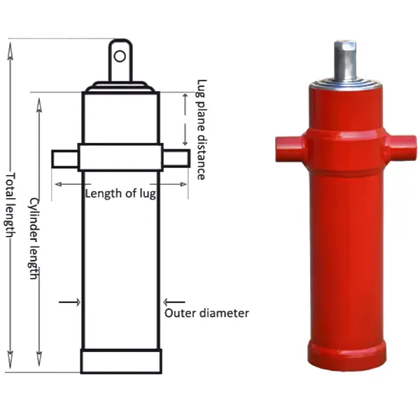
The choice between single-acting and double-acting lift cylinder configuration is the most consequential specification decision for a dump truck telescopic lift cylinder. Getting this wrong means the cylinder physically cannot complete the dump cycle — either it will not retract at all, or it will retract so slowly that cycle time becomes unacceptable.
| CRITERION | SINGLE ACTING | DOUBLE ACTING |
|---|---|---|
| Retraction force | Gravity / body weight only | Hydraulic pressure — active in both directions |
| Hydraulic lines required | 1 line | 2 lines |
| Retraction speed | Depends on body weight and back pressure | Controlled and consistent regardless of load |
| Overcenter body handling | Cannot retract — body stuck if over center | Active retraction pulls body back from over center |
| Construction complexity | Simple — low cost, easy to service | Complex internal passages — higher cost |
| Best for | Standard rear-tip dump trucks, trailers | Over-center bodies, refuse ejectors, special bodies |
For the vast majority of dump trucks — rear-tip bodies using a single-acting telescopic lift cylinder tipping standard aggregates, soil, or demolition waste — represents the correct and most cost-effective choice. The body weight is always sufficient to retract the lift cylinder the cylinder once the dump valve opens the exhaust path, and the single-line hydraulic circuit simplifies the hose routing. Double-acting cylinders are required only when the dump body geometry takes the cylinder over center (body hinge point passes below the cylinder top mounting as the body tips fully), or when the application involves near-horizontal ejection where gravity cannot assist retraction.
第 03 节
Stage Count and Force Progression
Stage count is the primary driver of three competing performance characteristics in a dump truck telescopic lift cylinder: collapsed length, force uniformity across the stroke, and service complexity. Selecting more stages reduces the collapsed lift cylinder length but introduces force drop-off as successive smaller-bore stages extend, and adds seal complexity that increases maintenance requirements.
2
STAGES
Collapsed: ~53% of stroke
Force drop: ~40%
Best force uniformity
Lowest maintenance
3
STAGES
Collapsed: ~37% of stroke
Force drop: ~55%
Most common choice
Balanced all-round
4
STAGES
Collapsed: ~29% of stroke
Force drop: ~65%
Long-body trucks
More seal points
5
STAGES
Collapsed: ~24% of stroke
Force drop: ~75%
Ultra-long trailers
Highest complexity
Force drop-off explained: In a telescopic lift cylinder, the first stage to extend is the largest-bore stage — it generates maximum force because force = pressure × bore area. As the first stage reaches full extension, the second (smaller) stage begins extending against the same system pressure. Since the bore is smaller, force is lower. This progressive force reduction means the telescopic lift cylinder delivers its highest force early in the tip cycle (when the body is heaviest and hardest to lift) and lowest force at the top of the stroke (when the body is nearly vertical and gravity assists). This natural characteristic is actually well-matched to the dump truck tip cycle — it is only problematic when the body geometry requires high force near the top of the stroke.
第 04 节
Front Mount vs Underbody — Configuration Guide
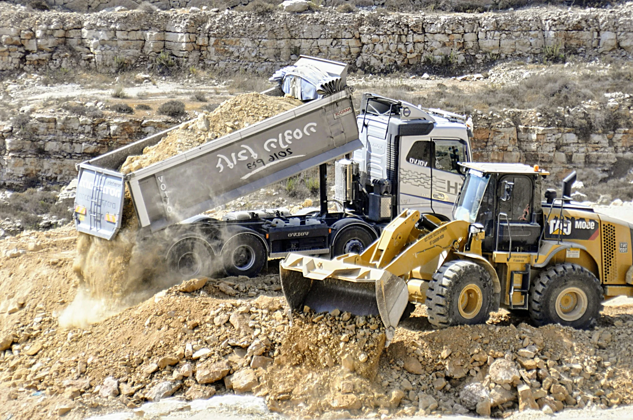
The mounting configuration determines the lift cylinder’s geometric efficiency throughout the tip cycle. A lift cylinder with identical bore and stroke will produce different effective tip forces depending on whether it is mounted front (vertical, pushing the body forward of the hinge) or underbody (diagonal, lifting under the body floor).
Between cab & body
✔
Favorable lift geometry — cylinder pushes near body centre of gravity, requiring less force throughout the stroke
✔
Single cylinder per truck — simpler hydraulic circuit, lower component count
✔
Better stability — upward thrust vector keeps body aligned on the sub-frame during tipping
✗
Requires sub-frame or A-frame structure — adds weight and cost to the body installation
✗
Reduces payload volume — cylinder and A-frame occupy space between cab and body
Diagonal under body floor
✔
Maximum payload volume — no A-frame intrusion into the space between cab and body
✔
Lower profile — suits low-clearance tipping bays and washing facilities
✗
Less favourable geometry — diagonal push angle means more force needed for same tip angle
✗
Exposed to road debris — cylinder rod and seals collect mud, grit, and moisture from below
✗
Harder to service — cylinder sits in the chassis envelope with limited access in the field
第 05 节
Specifications by Dump Truck Class
| TRUCK CLASS | PAYLOAD | BODY LENGTH | CYLINDER | STAGES | 压力 |
|---|---|---|---|---|---|
| Light duty (3.5–8 t) | 3.5–8 t | 3.2–4.5 m | Ø100–140 × 1 500 mm | 2–3 | 14–16 MPa |
| Medium duty (8–20 t) | 8–20 t | 4.5–5.5 m | Ø160–200 × 2 500 mm | 3 | 16–18 MPa |
| Heavy duty (20–40 t) | 20–40 t | 5.5–7.0 m | Ø220–280 × 4 000 mm | 3–4 | 18–21 MPa |
| Mining / ultra (40+ t) | 40–100+ t | 7.0–10+ m | Ø300–360 × 6 000+ mm | 4–5 | 21+ MPa |
Selection note: Bore diameter is the primary lift cylinder force variable; stage count controls collapsed length. Select bore for the required lift force at system pressure (F = P × π/4 × D₁²), then choose stage count to achieve a collapsed length that fits the chassis envelope. For standard duty dump trucks, the telescopic lift cylinder range covers light to heavy duty in both single and double acting configurations, with the full spectrum of telescopic hydraulic cylinders extending to mining-class applications.
第 06 节
Maintenance and Failure Prevention
Contamination accounts for over 80% of hydraulic system failures — and lift cylinders of this type are particularly vulnerable because the rod surfaces of all stages are exposed to the environment between tips. Every time the lift cylinder retracts, any grit or debris on the exposed rod surface is dragged back across the wiper seal and into the cylinder, acting as an abrasive that accelerates seal wear from the inside out.
MAINTENANCE PROTOCOL · DUMP TRUCK TELESCOPIC LIFT CYLINDER
Daily — Wipe rod surfaces before each operation
Use a clean rag to remove grit, mud, and road film from all exposed rod stages before starting the first tip of the day. This single step prevents up to 60% of avoidable seal failures.
Weekly — Inspect rod surface and check for oil seepage
Extend the cylinder to full stroke and inspect each lift cylinder stage surface for scoring, pitting, or chrome lifting. Any visible damage to the rod surface requires immediate stage replacement or re-chroming before the seal is destroyed.
Monthly — Grease trunnion pins, check fluid condition
Grease both trunnion pins and any clevis pin on the cylinder to prevent corrosion of the pivot bushings. Take a hydraulic oil sample and check for water contamination — a milky appearance indicates moisture ingress that will cause internal corrosion.
Annual — Full seal inspection and stage sequencing test
Cycle the lift cylinder at rated pressure and observe stage extension sequence — stages should extend from largest to smallest in smooth sequence. Any stage that hesitates, jumps, or extends out of sequence indicates a worn inter-stage seal that needs replacement before it fails completely in service.
COMMON FAILURE MODES · TELESCOPIC LIFT CYLINDER
STAGE DRIFT
Last stage (smallest bore) retracts incompletely, leaving the cylinder slightly extended at rest. Cause: back pressure buildup when retraction speed is too fast for the oil volume to drain — install a high-flow dump valve or slow the retraction by partially closing the dump valve.
ROD SCORING
Longitudinal scratches on the rod surface cause oil to bypass the rod seal and leak externally. Cause: debris on the rod surface dragged across the wiper seal. Prevention: daily rod wiping; replacement: hard chrome re-plating or stage replacement.
SLOW EXTENSION
Cylinder takes more than 30 seconds to reach full extension at rated pump flow. Cause: kinked supply hose, undersized pump, or partially blocked port fitting. Verify pump output and hose bore size match the cylinder’s required flow rate for target cycle time.
申请常见问题解答
Dump Truck Lift Cylinder Questions
Q 01
How do I calculate the correct bore size for a dump truck telescopic lift cylinder?
The required lift cylinder bore diameter is determined by the lift force needed at the beginning of the tip cycle — this is the highest-force point because the body is fully loaded and horizontal. Calculate the required cylinder force: take the body payload plus body structure weight (total tipping load, typically 1.2–1.5× the rated payload), multiply by the geometric factor for the mounting position (front mount: approximately 1.1–1.4; underbody: approximately 1.6–2.2), and this gives the required cylinder extension force in kN. Then calculate the first-stage bore: D = √(4F / πP) where F is force and P is system pressure. Apply a 20–25% safety margin to account for pump pressure variation, cold oil viscosity, and body geometry tolerance. Most engineers target first-stage extension force at 130–150% of the calculated minimum to provide adequate margin across all operating conditions.
Q 02
Why does my dump body drop too fast when I open the dump valve?
Uncontrolled rapid lift cylinder retraction is caused by insufficient restriction in the exhaust (return) path when the dump valve is opened. When a single-acting telescopic cylinder retracts, the oil in the barrel must flow back to the reservoir through the dump valve and return line. If that flow path is completely unrestricted, a heavy body can collapse the cylinder in 2–3 seconds — fast enough to create dangerous body swing, shock loading on the sub-frame, and hydraulic hammer in the return line. The correct fix is to install a high-flow dump valve with an adjustable metering orifice, or add a flow control valve in the return line, to limit the maximum exhaust flow rate and produce a controlled 6–10 second retraction time. Do not partially close the pump supply valve to slow retraction — this increases heat and creates cavitation in the cylinder as it tries to retract faster than oil can be supplied to the rod-end (in double-acting configurations).
Q 03
Can I replace a 3-stage lift cylinder with a 4-stage unit of the same stroke?
Yes, but only if the replacement unit fits the chassis envelope in the collapsed position and the mounting pin dimensions match. A 4-stage lift cylinder with the same stroke as the 3-stage original will have a shorter collapsed length — which may or may not be relevant depending on how much clearance exists between the body floor and the sub-frame when the body is down. The more important consideration is force profile: the 4-stage unit produces a different force drop-off pattern across the stroke, with lower force at full extension (smaller final stage bore) than the 3-stage original. If the original 3-stage cylinder was already marginal for lift force at the end of stroke, a 4-stage replacement may produce insufficient force to complete full tip angle under maximum payload. Verify the minimum force at full extension against the required tip force at the maximum body angle before specifying the additional stage.
Q 04
What is the correct hydraulic oil specification for a dump truck telescopic cylinder?
The dump truck telescopic lift cylinder requires mineral hydraulic oil meeting ISO 46 or ISO 68 viscosity grade depending on climate:
ISO 46
Ambient temperature 5°C to 40°C — standard climate; most widely used grade for dump truck telescopic systems
ISO 32
Cold climate operations below 5°C — lower viscosity improves cold-start flow and reduces the extension delay at low temperature
ISO 68
High ambient temperature above 40°C or high-cycle duty (mining) — higher viscosity maintains oil film at elevated temperature
All grades must include anti-wear additive package (ZDDP), rust and oxidation inhibitors, and anti-foam agents. Change the oil and filter every 500–1 000 operating hours, or immediately when the oil appears milky (water contamination) or dark brown (thermal degradation).
TELESCOPIC LIFT CYLINDER APPLICATION SUPPORT
Selecting Telescopic Lift Cylinders for Your Dump Truck?
Our application team provides telescopic cylinder selection support — bore sizing, stage count, mounting configuration, and pressure verification for any dump truck class from light-duty to mining. Contact us with your payload, body length, and chassis envelope dimensions.
编辑:Cxm














