
APPLICATION GUIDE · INDUSTRIAL LIFTING · SCISSOR LIFT TABLE CYLINDERS
Scissor Lift Table
液压缸
Sizing · Sync · Load-Hold
The hydraulic lift cylinder in a scissor lift table operates under a force condition that surprises most designers encountering it for the first time: the force required at the bottom of travel — when the scissor arms are nearly horizontal — is often 6–10 times greater than the force required at the top. This geometric force multiplication means that sizing the lift cylinder from the payload alone produces a dangerously undersized specification, and that correct scissor table cylinder selection is fundamentally a geometric problem before it is a hydraulic one.
Synchronisation
Load-Hold Safety
LIFT CYLINDERS · SCISSOR TABLE APPLICATION · JULY 2026
REFERENCE · SCISSOR TABLE LIFT CYLINDER DESIGN PARAMETERS
FORCE AT 8° ARM ANGLE
6–10× payload
Geometric force multiplication at near-horizontal arm angle — worst-case condition for lift cylinder sizing
CYLINDER BORE RANGE
80–200 mm
Light-duty 500 kg tables: 80–100 mm bore. Heavy-duty 10 t industrial tables: 150–200 mm bore
系统压力
16–20兆帕
Most scissor tables use 16–20 MPa systems — higher pressure reduces bore size but increases seal wear
LOAD-HOLD RATE
<5 mm/min
Maximum allowable platform descent under rated load with valves in neutral — verified at commissioning
第 01 节
Scissor Table Geometry and Force Multiplication
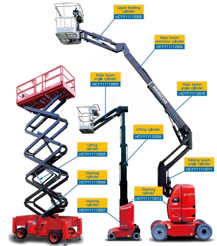 Scissor lift table hydraulic cylinder configurations — horizontal and angled cylinder mounting geometries produce very different force multiplication factors across the lift range. A horizontal cylinder at 8° arm angle sees 6–10× the load force; an angled cylinder at 30° from vertical at the same arm angle sees only 2–3×. The cylinder mounting geometry and position within the scissor arm system is therefore the primary variable in lift cylinder sizing, not the payload weight alone.
The fundamental challenge in scissor lift table lift cylinder sizing is that the table’s hydraulic cylinder does not bear the load directly — it transmits force through a lever system whose mechanical advantage changes continuously as the table rises. At the bottom of travel with near-horizontal scissor arms, the lever ratio is very unfavourable — the cylinder must generate enormous force to produce a small upward table movement. At the top of travel with steeper arm angles, the lever ratio improves dramatically and the required cylinder force falls.
HORIZONTAL CYLINDER FORCE MULTIPLIER vs SCISSOR ARM ANGLE
ARM ANGLE
8°
Force factor
7.1×
ARM ANGLE
15°
Force factor
3.7×
ARM ANGLE
25°
Force factor
2.1×
ARM ANGLE
35°
Force factor
1.4×
ARM ANGLE
45°
Force factor
1.0×
Values for horizontal cylinder mounted at the scissor arm midpoint. Actual values depend on the specific mounting geometry of each scissor table design.
The practical consequence of this force multiplication is that the lift cylinder for the scissor table must be sized for the worst-case condition — the arm angle at the bottom of travel — not the average condition or the payload weight alone. A scissor table that travels from 8° arm angle to 45° must have a hydraulic lift cylinder capable of generating 7× the payload force at the start of the lift cycle, even though it only needs 1× that force by the time the platform reaches full height.
第 02 节
Lift Cylinder Sizing — Worked Calculation
A systematic sizing calculation for a scissor lift table hydraulic cylinder proceeds through five steps. The example below uses a 2 000 kg capacity two-stage scissor table with 800 mm maximum platform travel, horizontal cylinder mounting, and a minimum arm angle of 12° at the lowest platform position:
Total load. Dead weight of platform + rated payload: 400 kg (platform) + 2 000 kg (load) = 2 400 kg. Convert to Newtons: 2 400 × 9.81 = 23 544 N. Add 15% dynamic factor for acceleration at cycle start: F_static = 23 544 × 1.15 = 27 076 N.
Force multiplication at minimum arm angle. At 12° arm angle with horizontal cylinder at midpoint: force factor = 1 / (2 × sin 12°) = 1 / (2 × 0.208) = 2.40×. Two cylinders share the load, so each cylinder sees: 27 076 × 2.40 / 2 = 32 491 N ≈ 32.5 kN per cylinder.
Safety factor. Apply 1.5× for personnel-carrying application: 32.5 × 1.5 = 48.8 kN design force per lift cylinder.
Bore calculation. At 18 MPa system pressure: D = √(4 × 48 800 / (π × 18 000 000)) = 0.0587 m = 58.7 mm. Round up to next standard bore: Ø 63 mm (delivers 62 kN at 18 MPa — 27% margin above design force).
Stroke calculation. The horizontal cylinder stroke = horizontal travel of the cylinder mount point across the full platform travel arc. For this geometry: stroke ≈ platform travel × (L_arm / H_cylinder_mount) × cos(θ_min). For this example: approximately 620 mm stroke for 800 mm vertical travel. Verify with a geometric construction or CAD model of the actual arm geometry.
For scissor tables with complex arm geometry or multi-stage configurations, the force calculation should be done using the table manufacturer’s engineering drawing rather than the simplified formula above. Send us the table geometry drawing and our engineers will calculate the required lift cylinder force and stroke and confirm the correct bore from the 举升缸 product range.
第 03 节
Single vs Dual Cylinder — Synchronisation
Wide scissor tables (platform width exceeding approximately 1.2× platform length) and all scissor tables serving as personnel platforms require two parallel lift cylinders — one on each side of the scissor arm assembly — to prevent lateral tipping of the platform under asymmetric loading. Single-cylinder configurations are only appropriate for narrow tables where the load can be assumed to remain close to the platform centreline.
PARALLEL FLOW CIRCUIT
Both lift cylinders are connected in parallel — receiving the same oil supply from the same directional control valve. In theory, equal flow produces equal extension speed. In practice, small differences in piston seal friction between the two cylinders cause one to lead the other by a few millimetres per cycle. Rephasing ports at the full-extension position reset this error on every cycle. A parallel flow circuit is adequate for most industrial scissor tables with non-personnel loads up to about 5 tonnes.
FLOW DIVIDER CIRCUIT
A gear-type flow divider splits the pump flow precisely between the two scissor table lift cylinders, maintaining synchronisation throughout the stroke rather than only resetting it at full extension. Flow dividers maintain synchronisation accuracy of ±2–5% of stroke across all positions, compared to the simple parallel circuit which can accumulate up to 15–20 mm error at mid-stroke before rephasing. Mandatory for personnel-carrying scissor table platforms, and recommended for automated loading tables where lateral tilt would damage the product being positioned.
第 04 节
Load-Holding Safety — POCV, Velocity Fuse and EN Standards
Every scissor lift table lift cylinder circuit must include a load-holding device that prevents uncontrolled platform descent if the hydraulic supply is interrupted. The type of device required depends on whether the platform carries personnel and the applicable safety standard:
GOODS-ONLY TABLES
EN 1570
EN 1570 (safety requirements for lifting tables) requires a load-holding device on the hydraulic circuit that prevents uncontrolled lowering if the circuit fails. A pilot-operated check valve (POCV) mounted at the lift cylinder port — not in the valve manifold — is the standard solution. The POCV holds the load indefinitely without leakage and only opens when the pilot signal is applied from the directional control valve during an intentional lowering command. Maximum permissible platform descent under EN 1570 with valves in neutral: 0.1% of travel per minute at rated load.
PERSONNEL-CARRYING
EN 280 / EN 1570-1
Scissor tables intended for use as personnel work platforms fall under EN 280 (mobile elevating work platforms) or EN 1570-1 (lifting tables with personnel). Both require a velocity fuse in addition to the POCV — the velocity fuse detects if the platform descends at more than the maximum controlled rate (typically equivalent to 2× the normal lowering speed) and closes automatically, locking the platform in position. EN 280 also requires a platform drift rate of less than 25 mm per 10 minutes under rated load with all controls in neutral, tested at commissioning and at each 6-monthly inspection.
Installation note: The POCV must be mounted directly at the lift cylinder cap-end port — a manifold-mounted POCV with hose between it and the cylinder port leaves a volume of oil between the valve and the piston that can slowly drain if the hose fails, allowing the piston to drift. For industrial-grade scissor table lift cylinders with integrated POCV, our 举升缸 technical team can advise on the available integrated valve configurations.
第 05 节
Seal and Circuit Specification by Application
| 应用 | 无聊 | 海豹 | 电路 | STANDARD |
|---|---|---|---|---|
| Light goods (500 kg, indoors) | 63–80 mm | NBR or PU | Single, POCV | EN 1570 |
| Industrial goods (2–5 t) | 100–125 mm | PU | Dual parallel, POCV | EN 1570 |
| Heavy industrial (5–15 t) | 140–200 mm | PU + PTFE backup | Dual + flow divider | EN 1570 + structural calc |
| Personnel work platform | 80–125 mm | PU 92 Shore A | Dual + flow divider + vel. fuse | EN 280 + EN 1570-1 |
| Food / pharma clean room | 80–125 mm | FKM or EPDM, NSF H1 oil | Dual + POCV | FDA / EHEDG compliant materials |
For heavy industrial scissor table lift cylinders requiring EN 1570 structural calculations and third-party certification, the 工业工程液压缸 range includes configurations with available design calculation packages and witnessed test certificates for scissor table applications requiring formal safety documentation.
第 06 节
Maintenance and Inspection Schedule
每周
Check for oil weeping at the lift cylinder rod seal and all port connections. Verify that the POCV holds the platform without descent when the controls are in neutral — hold for 5 minutes at mid-stroke with rated load; zero descent is the standard for goods tables, ≤5 mm for heavy industrial tables.
季刊
Oil sample for ISO cleanliness and water content. Replace hydraulic oil filter element. Measure lateral platform tilt at mid-stroke under rated load — exceeding 5 mm lateral difference between scissor arm sides indicates lift cylinder synchronisation failure. Lubricate all scissor pivot pins per table manufacturer’s specification.
6 MONTHS (PERSONNEL)
For personnel-carrying scissor platforms: formal inspection per EN 280 or EN 1570-1 by a competent person. Platform drift rate test at 125% rated load (EN 280: ≤25 mm/10 min). Velocity fuse function test. Full structural inspection of scissor arm pins and welds. All results documented in inspection logbook.
每年
Full lift cylinder seal replacement as preventive action on high-cycle tables (>100 cycles/shift). Rod chrome thickness measurement — re-chrome below 15 μm. Full hydraulic oil change. Pressure test of each lift cylinder at 1.5× working pressure after reassembly. Check POCV function by manually applying rated load and disconnecting pump — platform must hold without movement.
申请常见问题解答
Scissor Table Cylinder Questions
Q 01
Our scissor table platform tilts slightly to one side during lifting but returns to level at full height — is this a cylinder problem?
Yes, platform tilt during lifting that self-corrects at full extension is the classic symptom of synchronisation drift in parallel lift cylinders — exactly the condition that rephasing ports are designed to correct. One lift cylinder is extending slightly faster than the other (lower internal friction, receiving marginally more oil), causing the platform to tilt to the slower side. At full extension both lift cylinders reach the rephasing port position simultaneously and reset to equal extension. If the tilt is within 10 mm and causes no binding of the scissor arms or platform guide rollers, this is acceptable for a goods-only table. If the tilt is causing binding, structural stress on the scissor arms, or is visible to personnel on a work platform, the piston seal on the slower scissor table lift cylinder should be inspected and replaced — a worn piston seal allows bypass leakage that causes that cylinder to lag behind the parallel-supplied cylinder throughout the stroke.
Q 02
Why does our scissor table lower faster than expected when we release the lowering control — is the POCV set correctly?
Faster-than-expected lowering on release of the lowering control suggests that the lowering flow control valve (the valve that meters the oil leaving the lift cylinder during descent) is set to a higher flow rate than the original commissioning setting, or has developed internal bypass leakage. Check the lowering control flow valve setting against the commissioning record — if it has drifted, reset it. If the flow valve is correctly set and the platform still lowers faster than specified, the lift cylinder piston seal may have developed significant bypass leakage that allows internal flow from the cap-end to the rod-end during descent, supplementing the controlled lowering flow with bypass flow and increasing the effective descent rate. Measure piston seal bypass with a static pressure decay test — pressure decay faster than 2% per minute at rated load indicates piston seal replacement is required.
Q 03
Can we increase the lifting capacity of an existing scissor table by fitting a larger bore lift cylinder?
Not without a full structural re-engineering review of the entire scissor table. Increasing the lift cylinder bore allows higher loads on all components. The scissor arms, pivot pins, platform frame, and base frame were all designed for the original rated capacity. Increasing the lift cylinder bore to generate more force allows higher loads to be applied to these structural components, which may already be at or near their design limit at the original rating. A structural analysis confirming that all components have adequate capacity at the proposed new rating is required before the lift cylinder is changed. Additionally, the hydraulic power unit must be confirmed capable of supplying the increased flow at the higher pressure that a larger bore cylinder may require, and the POCV must be re-rated for the higher load capacity. In most cases, increasing the lift cylinder bore alone without concurrent structural reinforcement is unsafe — the correct approach for a capacity increase is to have the table formally re-rated by a structural engineer who reviews the entire assembly, not just the hydraulic lift cylinder.
Q 04
The lift cylinder on our scissor table makes a loud knock at the start of each lifting cycle — what is causing this?
A knock or bang at the start of the lifting cycle is almost always caused by air in the hydraulic circuit — specifically, a pocket of air trapped in the cap-end of the lift cylinder or in the supply hose that must be compressed before the oil column builds pressure and begins moving the piston. As the air is suddenly compressed to operating pressure at the moment of piston movement, it produces the characteristic knock. The correct fix is to bleed the circuit thoroughly by cycling the table 10–15 times without load at low pressure, allowing the air to migrate to the reservoir. If knocking recurs after bleeding, the source of air ingress must be found — a low reservoir level (allowing the pump to draw air at low load), a leaking hose fitting at the pump inlet, or a cavitating pump are the most common causes. A correctly bled circuit operating with an adequate reservoir level should lift silently from any position.
SCISSOR TABLE LIFT CYLINDER SPECIFICATION
Specifying Lift Cylinders for a Scissor Lift Table?
Send us your scissor table geometry drawing and rated capacity — our engineers calculate the correct bore, stroke, and load-hold specification and confirm the right lift cylinder from our full product range for your application and safety standard.
编辑:Cxm














