
ENGINEERING GUIDE · HEAVY-DUTY TIPPER · FRONT TOP LIFTING CYLINDERS
Front Top Lifting Cylinder
for Heavy-Duty
Tipper Trucks
The front top lifting cylinder is the dominant hydraulic actuator on large-bore tipper trucks in the 40–100 tonne payload class — the front top lift cylinder mounts vertically between a front-of-body A-frame and the chassis sub-frame, extending upward to push the body forward of its rear hinge point. With bore diameters from 150 to 180 mm and strokes from 3 360 to 5 390 mm, these cylinders deliver the force and travel needed to tip heavy-material bodies to 48–60 degrees while maintaining the compact collapsed length demanded by the chassis envelope.
3 360–5 390 mm Stroke
Front Top A-Frame Mount
LIFT CYLINDERS · TIPPER ENGINEERING · JULY 2026
PRODUCT REFERENCE · FRONT TOP LIFTING CYLINDER SPECIFICATIONS
BORE DIAMETER
150 / 180 mm
Two standard bore grades covering 40–100 t payload range
STROKE RANGE
3 360–5 390 mm
Extended stroke — accommodates 5–9 m body lengths at 48–60° tip
WORKING PRESSURE
20–25 MPa
Higher than light-duty telescopic — required by large bore at heavy payload
LIFT FORCE (Ø180)
≈ 509 kN
First-stage extension force at 20 MPa — adequate for 80–100 t payload bodies
第 01 节
What Defines a Front Top Lifting Cylinder
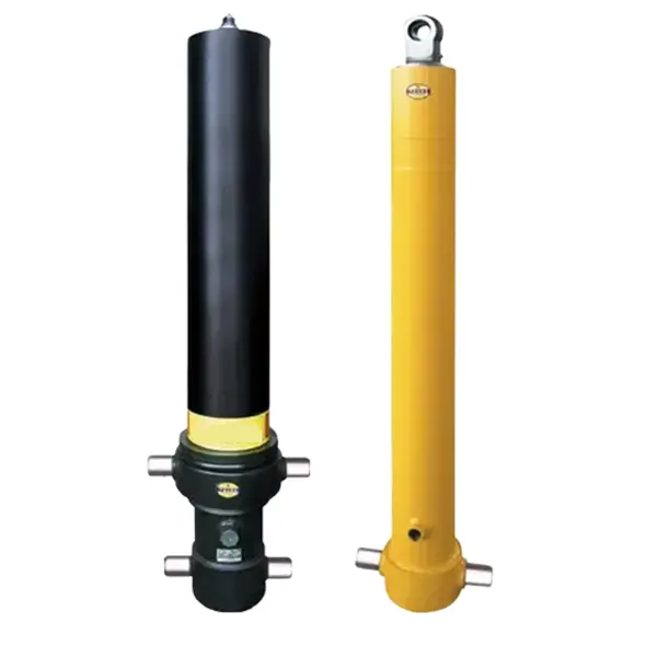
The term “front top lifting cylinder” identifies a lift cylinder by its a specific installation position within the tipper truck hydraulic system: the lift cylinder is mounted at the front of the body, pushing upward from a chassis-mounted sub-frame through an A-frame structure that bears against the front wall of the dump body near its top edge. This geometry places the push force directly above the body’s centre of mass in the horizontal rest position — the most mechanically efficient mounting angle for converting cylinder extension force into body rotation about the rear hinge.
Three characteristics distinguish the front top lift cylinder from other tipper configurations:
MOUNTING ANGLE
Near-vertical when body is at rest — the cylinder extends almost straight up, giving maximum mechanical advantage at the start of the tip cycle when the body is heaviest and gravity resistance is greatest.
FORCE DIRECTION
Push acts at the body’s front upper edge — the longest possible moment arm from the rear hinge, which minimises the cylinder extension force required to generate the tipping moment needed to raise the loaded body.
STROKE DEMAND
Longer stroke than underbody configurations for the same tip angle — because the lift cylinder pushes from the front of a long body, the arc that the A-frame crown travels demands more linear extension per degree of tip than a mid-body or rear-body push.
第 02 节
Why Large Bore (150–180 mm) at Heavy Payloads
Bore diameter is a direct function of the payload weight that the front top lift cylinder must tip. The relationship is straightforward: lift force equals hydraulic pressure multiplied by piston bore area. At a given system pressure, a larger bore produces more force. The 150 mm and 180 mm bore grades exist because the 40–100 tonne payload class requires forces that smaller-bore telescopic cylinders at standard 16–21 MPa system pressure simply cannot deliver.
BORE VS FORCE AT 20 MPa — FIRST STAGE EXTENSION
| BORE Ø | BORE AREA (cm²) | EXTENSION FORCE | EQUIV. LIFT MASS | 典型应用 |
|---|---|---|---|---|
| Ø 100 mm | 78.5 | 157 kN | ≈ 16 t | Light duty — 10–15 t payload |
| Ø 127 mm | 126.7 | 253 kN | ≈ 26 t | Medium duty — 20–30 t payload |
| Ø 150 mm | 176.7 | 353 kN | ≈ 36 t | Heavy duty — 40–60 t payload ← this product |
| Ø 180 mm | 254.5 | 509 kN | ≈ 52 t | Extra heavy — 60–100 t payload ← this product |
Equiv. lift mass = extension force ÷ 9.81 m/s². Actual tipping force needed is approximately 40–60% of payload mass due to A-frame geometry advantage — meaning a Ø180 mm bore provides significant safety margin for 80–100 t payloads.
The full 举升缸 range covers all bore grades from 50 to 360 mm. The practical reason for two bore grades — rather than a single intermediate size — is that tipping regulations require a minimum tip angle for the lift cylinder to achieve of 48 degrees for aggregate materials to fully discharge. At 48 degrees, the front top lift cylinder is extending against a significant component of body weight resolved back along the lift cylinder axis. The Ø150 mm bore provides adequate margin for 40–60 t payloads at this condition; the Ø180 mm bore is required when payloads exceed 60 tonnes or when system pressure is limited to below 20 MPa by the truck’s PTO pump driving the lift cylinder hydraulic circuit.
第 03 节
Stroke Selection and Body Geometry
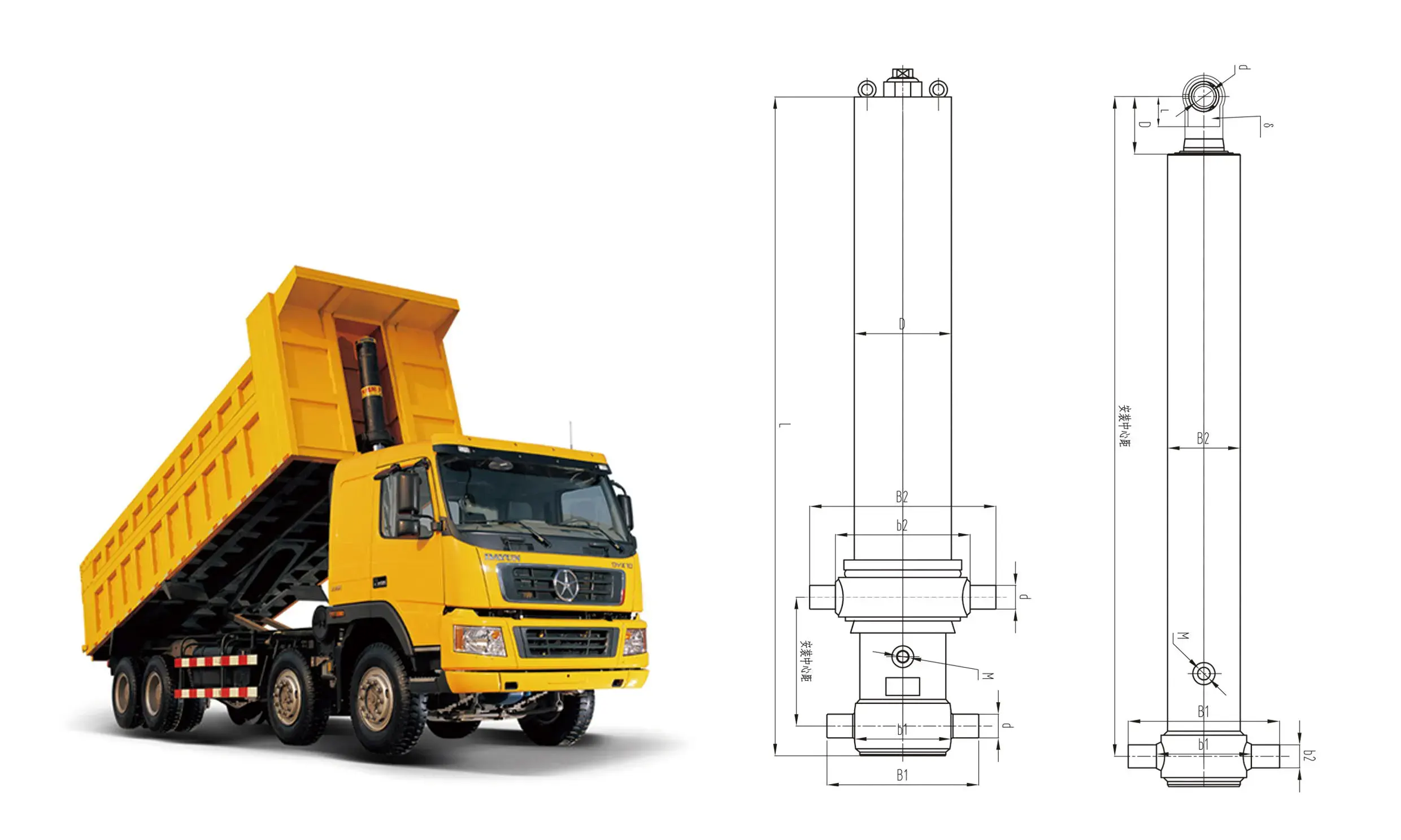
The stroke for the front top lift cylinder is independent of bore diameter — it is determined entirely by the body geometry: how far the A-frame crown must travel to rotate the body from the horizontal rest position to the target tip angle. The calculation requires three lift cylinder geometry measurements from the truck body drawing:
BODY LENGTH
Distance from rear body hinge to the front wall inside face, measured along the body floor.
Typical range: 5 000–9 000 mm
A-FRAME HEIGHT
Vertical distance from the body floor level to the A-frame crown pin centre — where the cylinder top eye connects.
Typical range: 800–1 400 mm
TARGET TIP ANGLE
The body angle at full cylinder extension — set by material material discharge requirements and body geometry.
Typical: 48–60° for aggregate materials
INDICATIVE STROKE SELECTION · BODY LENGTH vs TIP ANGLE (A-FRAME HEIGHT 1 000 mm)
| BODY LENGTH | 48° TIP | 52° TIP | 60° TIP |
|---|---|---|---|
| 5 000 mm body | ≈ 3 360 mm | ≈ 3 680 mm | ≈ 4 150 mm |
| 6 500 mm body | ≈ 3 980 mm | ≈ 4 320 mm | ≈ 4 900 mm |
| 7 500 mm body | ≈ 4 520 mm | ≈ 4 890 mm | ≈ 5 390 mm |
| 9 000 mm body | ≈ 5 120 mm | ≈ 5 560 mm | Custom stroke |
Values are indicative for A-frame height of 1 000 mm above body floor. Actual stroke must be calculated from the specific A-frame geometry drawing. The product range of 3 360–5 390 mm covers the most common 5 000–7 500 mm body configurations at 48–60° tip angle.
第 04 节
A-Frame Mounting and Installation

The A-frame mounting imposes specific alignment requirements that determine lift cylinder rod seal life that must be satisfied before the first tip cycle. Misalignment between the sub-frame mounting plate and the A-frame crown creates side-loading on the lift cylinder rod — the single most common cause of premature rod seal failure and barrel distortion on front top cylinders in heavy-duty service.
INSTALLATION ALIGNMENT CHECKLIST
步骤 1
Verify sub-frame mounting plate is level. With the truck on a flat surface and body fully down, the bottom mounting plate must be within 1° of horizontal in both the longitudinal and transverse planes. Use a precision level — a 2° longitudinal error creates 35–50 mm of lateral offset at full extension, generating enough side load to destroy the rod seal within 200 tip cycles.
步骤 2
Align the A-frame crown pin centreline with the cylinder centreline. When the body is at rest and the lift cylinder is fully collapsed, the top eye pin must be directly above the bottom flange pin with no transverse offset. Measure with a plumb line dropped from the crown pin — the string must pass within 5 mm of the bottom flange pin centre.
步骤 3
Confirm top eye pin has lateral float. The top eye pin must be free to pivot ± 3–5° laterally to accommodate the arc the A-frame crown traces as the body tips rearward. If the crown pin is rigidly locked in both axes, every tip cycle generates a bending moment on the cylinder rod proportional to the tip angle.
VERIFY
First-tip inspection. After the first full tip cycle, inspect the entire rod surface for contact marks or polishing — bright marks on one side of the rod indicate lateral loading. Any contact marks require immediate A-frame realignment before continued operation.
第 05 节
Sealing, Material and Corrosion Engineering
The front top lifting cylinder on a heavy tipper operates in an extreme environment — high tip frequency (20–100 cycles per day in quarry or mining operations), exposure to aggregate dust and moisture at every retraction, and the structural loads of bodies carrying 40–100 tonne of dense rock. The seal and material specification for this large-bore lift cylinder reflects these demands directly.
SEAL SPECIFICATION
Rod Wiper
Double-lip polyurethane wiper with integrated metal scraper — the metal scraper removes coarse aggregate particles before the polymer lip contacts the rod, preventing grit embedding in the seal lip that causes rapid seal destruction.
Rod Seal
Polyurethane loaded lip seal, 92–95 Shore A — abrasion resistant with the flexibility to conform to minor rod surface imperfections that inevitably develop over high-cycle service.
Inter-Stage Seals
PTFE-backed NBR piston seals at each lift cylinder stage — low friction ensures consistent stage sequencing under cold-oil conditions and prevents pressure lock between stages on retraction.
工作温度
−30°C to +120°C for the polyurethane grades specified — covers arctic winter operation without cold-crack risk and sustained summer operation in hot-climate quarries.
MATERIAL SPECIFICATION
Barrel
Cold-drawn seamless steel tube for the lift cylinder barrel, minimum yield strength 355 MPa (S355 or equivalent) — honed to Ra 0.4 μm for consistent seal contact for consistent seal contact surface across all stage diameters.
Piston Rod / Stages
Induction-hardened lift cylinder stage rod, minimum surface hardness 650 HV, hard-chrome plated to 30–40 μm thickness — chrome depth chosen to survive the rod wear that occurs when aggregate dust bypasses the wiper under extreme exposure.
Outer Surface Treatment
Zinc-phosphate pre-treatment plus 2-coat epoxy primer and polyurethane topcoat — minimum 120 μm dry film thickness, corrosion resistance to 500 hours salt spray per ISO 12944 C4 specification for industrial environments.
Welded Joints
Full penetration welds on barrel end-caps and flange plates, 100% magnetic particle inspected — critical given the cyclic bending loads on a large-bore front top lift cylinder at heavy payloads at heavy payloads.
第 06 节
Maintenance Schedule and Failure Patterns
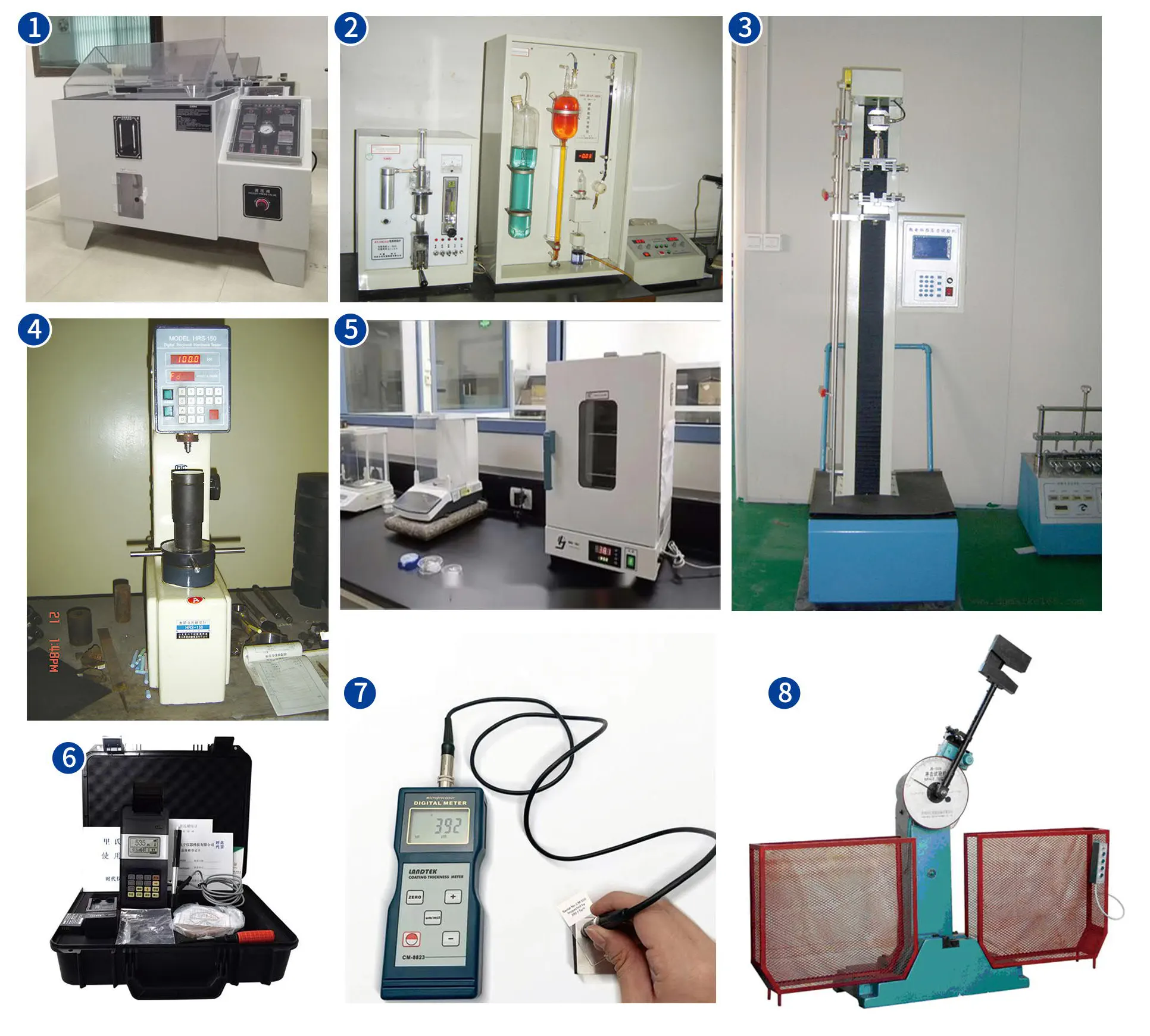
High-cycle tipper operation subjects the front top lift cylinder to an extreme environment compresses the maintenance timeline significantly compared to construction dump truck applications. A quarry truck runs 60–100 tip cycles daily — each cycle demanding a full lift cylinder extension and retraction will accumulate 18 000–30 000 tip cycles per year — equivalent to 10–15 years of light construction service. The following schedule reflects this intensity:
Daily
Before first tip
Wipe all exposed rod stages of the lift cylinder from grit and dust before the first tip. Check that the lift cylinder top eye pin grease nipple is present and grease the pin. Visually inspect the outer cylinder surface for dents or impact damage from loose rock.
Weekly
500–700 cycles
Extend the front top lift cylinder to full stroke and inspect every stage surface under direct light. Check for oil seepage at the base of each stage during the full-extension hold. Verify the A-frame crown pin grease pocket — regrease if grease has squeezed out or darkened.
Monthly
2 000–3 000 cycles
Check A-frame alignment with a steel rule or laser across the sub-frame pin and crown pin centrelines — any misalignment detected requires immediate A-frame adjustment to protect the lift cylinder rod. Inspect the bottom flange bolts for loosening (re-torque to manufacturer specification). Check the lift cylinder hydraulic oil sample for contamination or water ingress.
Annual
18 000–30 000 cycles
Full lift cylinder seal kit replacement on a preventive basis in high-cycle quarry operation — replacing seals at a scheduled interval is less costly than an unplanned seal failure during a loading cycle. Measure the lift cylinder rod chrome thickness using an eddy-current gauge — if chrome is below 15 μm remaining, send the rod for re-chroming. Verify stage sequencing at rated flow and cold-start pressure. For comparison with other heavy-duty tipper cylinder configurations, see the 伸缩式液压缸 range.
FAILURE PATTERN RECOGNITION · FRONT TOP LIFTING CYLINDER
Most common presentation
Cause: Lift cylinder rod seal failure — usually due to grit abrasion from insufficient rod wiping or lateral loading from A-frame misalignment. Action: Immediately replace rod seal kit; inspect rod surface for scoring; check A-frame alignment before reinstalling.
Cold starts or after long rest
Cause: High oil viscosity at low temperature, or inter-stage seals swollen from extended static contact — common after weekend shutdown. Action: Allow hydraulic oil to warm to operating temperature before full-load tipping; if persistent, switch to ISO 32 grade for winter operation.
After rock fall impact
Cause: Direct impact from discharged rock or overhanging material on the extended lift cylinder stages — a hazard in quarry operation where the tipping angle brings the outer stage within reach of falling material. Action: Any barrel dent or visible bend is a lift cylinder replacement trigger — do not continue operation as the stage will jam or the seal will be destroyed within a few further cycles.
申请常见问题解答
Front Top Lifting Cylinder Questions
Q 01
How do I determine whether I need the 150 mm or 180 mm bore grade?
The lift cylinder bore selection follows from the maximum tip force required at the start of the tip cycle, which is determined by the loaded body weight and the A-frame geometry. Calculate the tipping moment for the lift cylinder: (total loaded body weight × distance from rear hinge to body centre of gravity). Then calculate the resisting moment at the lift cylinder: (cylinder extension force × distance from rear hinge to A-frame crown pin). Set these equal and solve for cylinder extension force, then add a 30% margin for static friction breakaway. If the required force is below 400 kN, the 150 mm bore at 20 MPa is sufficient. If it exceeds 400 kN, or if your system pressure is below 20 MPa, specify the Ø180 mm lift cylinder. For most 40–60 t payload tippers, the 150 mm bore is the standard selection; the 180 mm bore is standard for 60–100 t applications.
Q 02
Can the front top lifting cylinder be used on side-tipping bodies?
No — the front top lift cylinder is designed exclusively for rear-tipping bodies where the hinge is at the rear and the push is applied at the front. In a side-tipping body, the hinge is along one side and the push must be applied at the opposite side edge. Using a front top lift cylinder on a side-tipping body would require a fundamentally different sub-frame geometry and would expose the cylinder to severe lateral loading that no lift cylinder seal system can withstand throughout the tip cycle, as the push direction is perpendicular to the intended tipping plane. Side-tipping bodies typically use either underbody hoist systems or dedicated side-mounted cylinders with clevis-to-clevis mounting that allows the correct angular freedom during the tip arc.
Q 03
What is the correct hydraulic pump specification for a 180 mm bore front top cylinder?
A Ø180 mm bore lift cylinder at 5 000 mm stroke (3 stages) contains approximately 127 litres of hydraulic oil volume at full extension. To achieve a 60-second full extension time (a reasonable tip cycle for heavy quarry operation), the pump must supply 127 litres per minute at rated lift cylinder pressure. Most heavy-duty tipper PTO pumps in the 180 mm bore class operate at 80–140 l/min, meaning the full extension time is typically 55–95 seconds depending on pump flow rate and system efficiency losses. Verify that the truck’s PTO engagement speed and the pump’s rated flow at that PTO speed match this requirement — a pump that is undersized for the cylinder volume will produce excessively slow tips that reduce site productivity, while an oversized pump produces no benefit as the relief valve limits maximum pressure.
Q 04
How long does a large-bore front top lifting cylinder last in high-cycle quarry service?
In a quarry truck the front top lift cylinder accumulates 15 000–25 000 tip cycles per year, 250 days per year, the lift cylinder . Those. Under these conditions, the rod seal kit on the lift cylinder typically requires replacement at 12–18 months of service (15 000–30 000 cycles) if the daily rod-wiping protocol is followed consistently. Without daily rod wiping, seal life drops to 4–6 months in dusty quarry conditions. The barrel and stages of the lift cylinder have a longer service life a longer service life — typically 60 000–100 000 cycles before bore honing or rod re-chroming is required, equivalent to 3–7 years of high-cycle quarry operation. The A-frame crown pin and bushings require replacement at approximately 20 000–30 000 cycles (1–2 years in intensive quarry service). The overall lift cylinder service life, measured to the point of barrel replacement, is typically 8–12 years in quarry service when maintained according to the schedule outlined in Section 6.
FRONT TOP LIFTING CYLINDER SPECIFICATION SUPPORT
Specifying a Front Top Lift Cylinder for Your Tipper?
Our application team verifies bore, stroke, and mounting geometry against your body drawing before order — ensuring the front top lift cylinder fits your A-frame and chassis envelope without modification.
编辑:Cxm














