
Aerial Access Equipment Series · Monograph XI
高所作業台用メインブームリフトシリンダー
Aerial work platforms (AWPs) and mobile elevating work platforms (MEWPs) operate under uncompromising functional safety mandates, elevated heights, and strict structural deflection limits. This 2500+ word engineering masterclass examines the mechanics, tribology, and structural design of double-acting welded main boom lift cylinders. We analyze high-reach elevation kinematics, 42CrMo alloy steel metallurgy, thick-wall barrel hoop stress mechanics, integrated end-of-stroke cushion dampening, and advanced methods to prevent barrel deformation under severe eccentric wind and side loads.
厚肉バレル設計
Cushion Dampening
Engineering Specifications Matrix for AWP Main Boom Lift Cylinders
The following engineering parameters establish the structural, material, safety, and operational standards required for double-acting main boom lift cylinders deployed in telescoping and articulating boom aerial work platforms.
| エンジニアリングパラメータ | Aerial Work Platform Specification Standard |
|---|---|
| 機器のカテゴリーと用途 | Construction & Access Equipment / Aerial Work Platform (AWP / MEWP) |
| サブシステム動作プロファイル | Main Boom Elevating Circuit / Double-Acting Controlled Smooth Elevation |
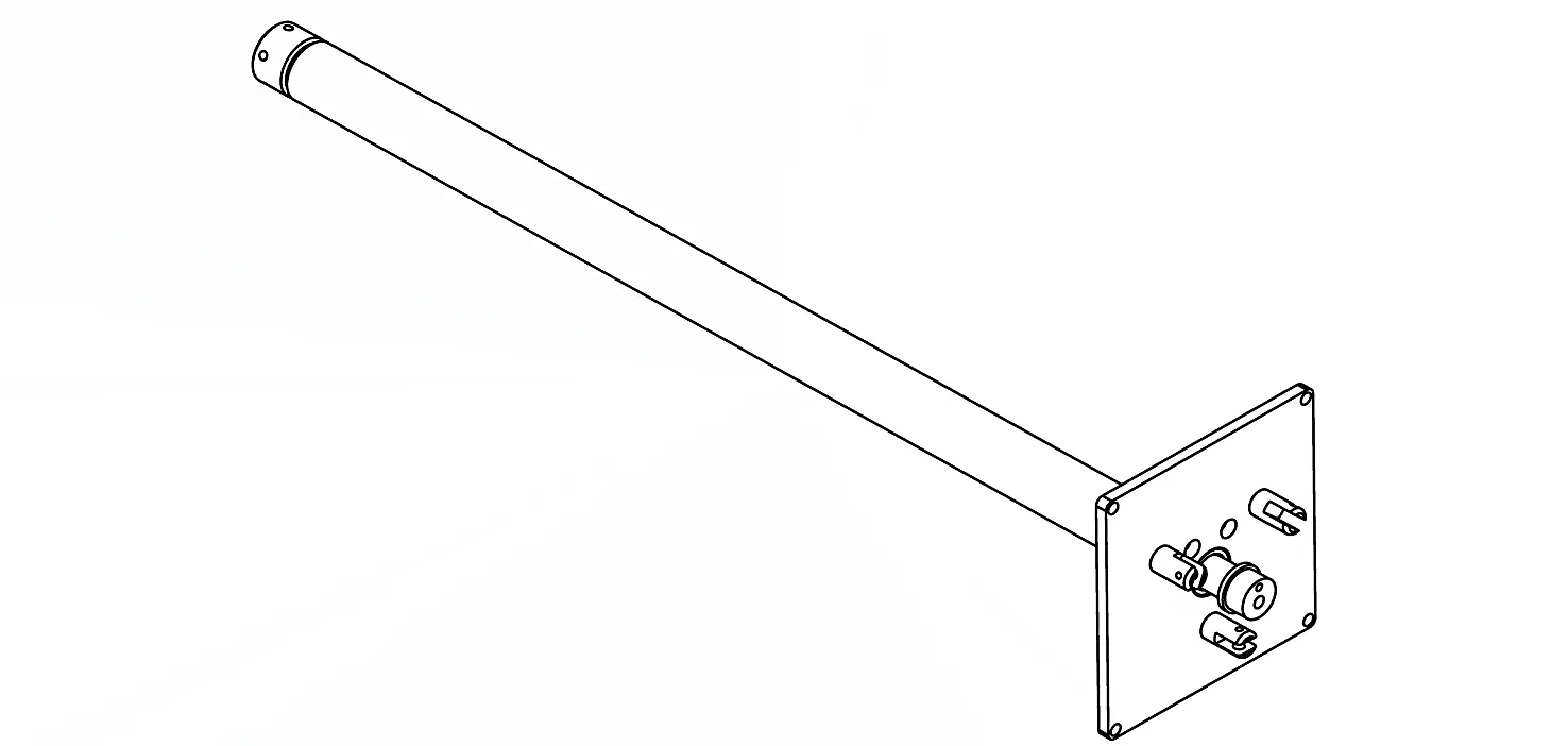
| 油圧シリンダー名 | Main Boom Lift Cylinder Assembly (HCYY Series Compliant) |
| 動作モードと構造タイプ | Double-Acting Piston Type (Linear Push/Pull Motion) |
| 製造業 建設業 | Full-Penetration Welded Heavy-Wall Architecture (AWS D1.1 Verified) |
| 材料系冶金 | 42CrMo Alloy Steel (Seamless Tube Barrel & Solid Forged Rod) |
| 表面仕上げとメッキ | 微細亀裂入り硬質クロムめっき(30~40μm)/HRC 58~62誘導焼入れケース |
| 環境評価クラス | High Elevation Exposure + Severe Lateral Wind Loads + Eccentric Payload Off-Center |
| 労働条件概要 | Ultra-Smooth Variable Speed Lifting + Zero Motion Jerk + Strict Position Holding |
| 主要な故障が軽減されました | Cylinder Barrel Deformation, Ovalization, & Mid-Stroke Oil Bypass Leakage |
| 推奨されるエンジニアリングの重要ポイント | Heavy Thick-Wall Barrel Design + Integrated Dual End-of-Stroke Hydraulic Cushions |
| Nominal Pressure & Safety Margin | 25.0 MPa to 31.5 MPa Working Pressure / 4:1 Structural Safety Factor (EN 280) |
AWP Boom Elevation Kinematics and Functional Safety Standards
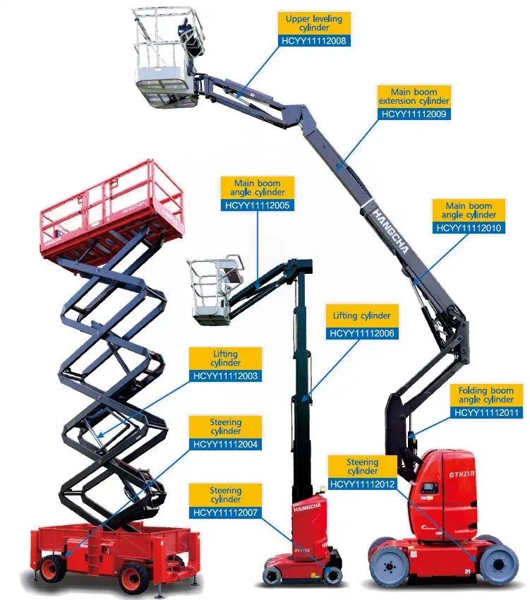
Aerial work platforms—including telescopic boom lifts, articulating boom lifts, and truck-mounted insulated access platforms—are engineered specifically to transport personnel, tools, and materials to elevated work positions ranging from 15 to over 60 meters above ground level. Unlike earthmoving machines where hydraulic actuators push against static dirt or rock, an AWP boom lift cylinder operates under strict human life safety standards mandated by international safety directives such as EN 280, ANSI/SAIA A92.20, and ISO 16368.
The primary hydraulic lifting cylinders for aerial work vehicles are located at the base of the main boom structure. Mounted between the rotating superstructure turntable and the bottom pivot section of the primary boom arm, this cylinder provides the angular elevation torque required to raise the entire multi-section telescoping boom assembly and the occupied platform basket.
Smooth Elevation Profiling and Human Comfort Thresholds
When an operator is standing in a basket extended 45 meters in the air, any tiny hydraulic pressure surge, mechanical stick-slip judder, or sudden deceleration inside the lift cylinder is magnified down the length of the boom. A 1 mm sudden jerk at the cylinder piston rod translates into a severe, multi-foot sway at the platform basket, creating extreme panic and structural dynamic resonance.
Consequently, the main boom lift cylinder must deliver completely linear, continuous, vibration-free elevation velocity. This motion profile is managed by electro-hydraulic proportional valves paired with pilot-operated load-holding counterbalance valves mounted directly onto the cylinder base manifold, eliminating line burst risks.
Mechanical Force Equations Under Varying Boom Angles
The lifting force Fcylinder required from the main boom cylinder varies non-linearly as a function of the boom elevation angle (θ). The maximum hydraulic thrust load occurs when the boom is near its horizontal position (θ ≈ 0°), where the moment arm distance between the payload center of gravity and the main boom pivot pin is at its maximum:
Wはどこでboom そしてWbasket are the weights of the boom structure and platform basket, Lboom_cg and L合計 are the respective moment arms, Lcyl_pin is the distance from the main pivot to the cylinder attachment pin, and α is the acute angle formed between the cylinder centerline and the boom structure. Because sin(α) is small when the boom is stowed, the initial breakaway force demanded from the cap-end chamber is exceptionally high, requiring operating pressures up to 31.5 MPa.
Root Cause Failure Analysis: Barrel Deformation, Ovalization, and Mid-Stroke Leakage
In field operations, main boom lift cylinders on high-reach AWPs encounter severe complex stress combinations. Unlike stationary industrial actuators, an AWP lift cylinder is subject to heavy column compression, high internal pressure, and strong multi-axis bending caused by lateral wind loads and eccentric platform loading.
The primary structural failure mode for undersized or thin-walled AWP lift cylinders is Barrel Deformation (Cylinder Ovalization). This issue manifests as permanent or elastic out-of-round deformation of the cylinder barrel walls near the center of the stroke.
The Physics of Combined Bending and Internal Pressure Hoop Stress
When an aerial platform extends 40 meters laterally with two workers in the basket during a gusting 45 km/h crosswind, the wind force induces a powerful twisting moment across the main boom structure. This torsional moment translates into a transverse side force (F側) acting directly on the extended lift cylinder rod end.
This side force bends the extended cylinder assembly into an arc. Simultaneously, the internal hydraulic fluid pressure (Pハイド) exerts a circumferential hoop stress (σフープ) outward against the inner barrel wall:
If the wall thickness t壁 is insufficient, the combination of internal hoop stress (σフープ) and external bending stress (σ曲げ) causes the circular cross-section of the seamless steel barrel to distort into an ellipse (ovalization). Even an ovalization distortion of just 0.08 mm destroys the concentric fit required between the main piston seals and the barrel inner wall.
Destructive Cascade of Mid-Stroke Internal Oil Bypass
Once barrel ovalization occurs, it initiates a destructive mechanical cascade that compromises machine safety and operational control:
1. Loss of Radial Seal Compression
As the piston travels into the ovalized mid-stroke region of the barrel, the gap between the piston body and the major axis of the distorted barrel widens, reducing the radial squeeze on the primary PTFE or polyurethane piston seal.
2. High-Pressure Fluid Jetting
High-pressure oil from the cap end jets past the uncompressed seal lips into the low-pressure rod chamber. This micro-bypass cuts pathways into the soft seal material, accelerating seal degradation.
3. Uncontrolled Platform Drift
Internal fluid bypass causes the main boom to slowly sag or bounce under load. The machine’s safety system detects this uncommanded movement and triggers an emergency lockout, stranding operators elevated aloft.
Recommended Configuration: Thick-Wall Engineering and Cushion Dampening
To mitigate barrel deformation, withstand severe wind loads, and ensure smooth boom movement, main boom lift cylinders for aerial platforms require an optimized engineering configuration centered around “Heavy Thick-Wall Barrel Design” and “Integrated Hydraulic Cushion Dampening”.
Thick-Wall Barrel Design Criteria for Deformation Prevention
Engineers optimize barrel wall thickness by applying Lamé’s thick-wall cylinder equations rather than simplified thin-wall approximations. A cylinder barrel is classified as a thick-walled vessel when the wall thickness ratio exceeds 10% of the inner radius (t壁 / R内部 > 0.10).
For AWP main boom lift cylinders, the wall ratio (K = D外 / D内部) is specified between 1.25 and 1.40. Increasing the wall thickness provides two structural benefits: it reduces peak internal hoop stress to keep material response well within the elastic range, and it provides structural rigidity that keeps barrel ovalization under maximum side-bending moments well below 0.015 mm.
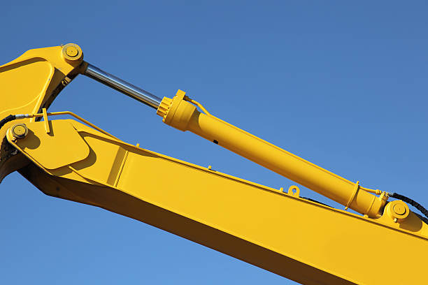
Close up view of a hydraulic piston belonging to an excavator.For similar pictures go to
Dual End-of-Stroke Integrated Hydraulic Cushions
To eliminate violent mechanical shocks when the boom reaches full extension or lowers completely into its stowed cradle, the lift cylinder incorporates precision internal hydraulic cushions at both stroke extremes:
- ▸
Tapered Spear Extension Cushioning: As the piston approaches the end of its extension stroke, a ground steel spear attached to the piston rod enters a restrictive port cavity in the cylinder head. This movement progressively restricts exiting fluid flow, creating backpressure that decelerates the heavy boom smoothly over the final 30 mm to 50 mm of travel. - ▸
Cap-End Retraction Cushioning: During full retraction into the transport cradle, a floating sleeve or cushion plunger enters the cap-end oil passage, throttling fluid escape to prevent the heavy boom structure from slamming into the chassis stops. - ▸
Integrated Reverse Free-Flow Check Valves: Parallel check valves are built into the cushion passages to ensure full oil flow is restored immediately when fluid direction reverses, allowing instant breakaway response without lag.
Specifying an engineered thick-wall hydraulic lift cylinder equipped with dual hydraulic cushions prevents barrel deformation and protects platform workers from dynamic motion shock.
Metallurgical Engineering: 42CrMo Alloy Steel System
The structural safety mandates governing human access equipment prohibit using standard commercial carbon steel for critical boom cylinders. Main boom lift cylinders deployed in AWPs utilize “42CrMo alloy steel” (conforming to GB/T 3077, equivalent to AISI 4140 / 42CrMo4) for both the heavy-wall seamless cylinder barrel and the solid piston rod.
Quenching and Tempering Heat Treatment Kinetics
Raw 42CrMo steel forgings and seamless thick-walled tubes undergo full Quenching and Tempering (Q&T) processing. The steel is austenitized at 850°C to 880°C, quenched in polymer or oil to achieve a fully martensitic grain structure, and tempered at 560°C to 620°C to produce tempered martensite.
This heat treatment increases the core yield strength (σ0.2)から 850 MPa を超える極限引張強度(σb) to over 1000 MPa, with Charpy V-notch impact toughness exceeding 45 J at -20°C. Following Q&T processing, the solid piston rod undergoes medium-frequency induction hardening to a depth of 2.5 mm to 4.0 mm, achieving a surface hardness of 58 to 62 HRC to resist scratching and indentation.
Mechanical Performance Comparison
| 鋼材グレード | 降伏強度(σ)0.2) | 引張強度(σ)b) | シャルピー衝撃エネルギー(-20℃) |
|---|---|---|---|
| AISI 1045(中炭素鋼) | ≥ 355 MPa | ≥ 600 MPa | ≤ 20 J |
| ST52-3 / E355(DOMチューブ) | ≥ 355 MPa | ≥ 520 MPa | ≥ 27 J |
| 42CrMo合金鋼(焼入れ・熱処理済み) | ≥ 850 MPa | ≥ 1000 MPa | ≥ 45 J |
Frequently Asked Questions: AWP Main Boom Lift Cylinder Engineering
What causes hydraulic boom drift on an aerial work platform basket?
Hydraulic boom drift on an AWP is caused by two main factors: internal oil leakage past the main boom lift cylinder piston seals (often due to barrel ovalization or worn U-cup seals), or thermal fluid contraction as hot hydraulic oil cools while elevated. Severe drift can also occur if the pilot-operated counterbalance valve mounted on the cylinder manifold has contaminated seat surfaces. A mechanical isolation test must be performed to identify whether the leak is internal to the cylinder or within the control valve block.
Why is a thick-wall barrel design critical for high-reach AWP boom lift cylinders?
High-reach AWPs expose the main boom cylinder to extreme bending forces from lateral crosswinds and eccentric basket loads. Thin-walled cylinder barrels can undergo elastic or permanent ovalization distortion under these combined stresses. Distortion reduces the radial pre-load on the piston seals, causing high-pressure oil to jet past the piston and resulting in uncommanded boom drift. A thick-wall 42CrMo barrel maintains its circular cross-section under severe side-bending loads, ensuring reliable seal contact.
How do integrated end-of-stroke hydraulic cushions protect platform operators aloft?
Integrated hydraulic cushions use tapered spears or plungers near the end of the cylinder stroke to progressively restrict exiting oil flow. This throttling action creates a controlled hydraulic backpressure cushion that decelerates the heavy boom structure smoothly over the final 30 mm to 50 mm of stroke travel. Eliminating end-of-stroke impact prevents sudden dynamic bouncing at the basket, protecting platform occupants from motion shock and reducing fatigue stresses on the boom pins.
Why is 42CrMo alloy steel preferred over standard carbon steel for AWP lift cylinders?
42CrMo alloy steel provides a yield strength exceeding 850 MPa following quenching and tempering—more than double the yield strength of standard AISI 1045 or ST52 steel. It also delivers Charpy V-notch impact energy exceeding 45 Joules at -20°C. This combination of high yield strength and sub-zero toughness prevents structural rod bending and brittle barrel cracking during severe dynamic loading in winter conditions.
戦略的調達と総所有コスト(TCO)
For rental fleet operators and equipment maintenance engineers managing aerial work platforms, cylinder failures impact machine availability and safety compliance. Sourcing low-cost replacement cylinders built with thin-walled barrels or standard carbon steel often leads to repeat boom drift issues, premature seal wear, and elevated total maintenance costs over the life of the machine.
Equipment engineers can evaluate technical options across specialized aerial machinery hydraulic cylinders technical options to review material certifications, cushion performance, and mounting dimensional standards. Equipping platforms with high-performance HCYY series aerial work vehicle cylinders engineered with 42CrMo thick-wall barrels, hard chrome surface protection, and dual hydraulic cushions ensures reliable elevation performance, safety compliance, and low long-term operating costs.
Ensure Maximum Safety and Elevation Precision Aloft
Eliminate mid-stroke barrel ovalization, prevent boom drift, and deliver smooth motion for elevated workers. Explore our series of double-acting, 42CrMo thick-wall main boom lift cylinders engineered for aerial work platforms.














