
APPLICATION GUIDE · CONSTRUCTION EQUIPMENT · HYDRAULIC LIFT CYLINDERS
Lift Cylinders for
Construction Equipment
Excavator · Loader · Crane · AWP
Construction equipment operates some of the most heavily loaded and highest-duty hydraulic cylinders in any industry — from excavator boom and arm cylinders that endure thousands of digging cycles daily under combined forces exceeding 400 kN, to aerial work platform mast cylinders that must hold personnel safely at heights of 20 metres or more. Each construction equipment type imposes a unique combination of load magnitude, duty frequency, contamination environment, and safety requirement on its hydraulic cylinders.
Mobile Crane
Aerial Work Platforms
LIFT CYLINDERS · CONSTRUCTION APPLICATION ENGINEERING · JULY 2026
REFERENCE · CONSTRUCTION LIFT CYLINDER APPLICATION PARAMETERS
口径範囲
50–250 mm
Small AWP scissors to large crane outrigger and boom cylinders
システム圧力
20–35 MPa
Higher than most mobile applications — compact equipment demands small bores at high pressure
CYCLE FREQUENCY
100–3 000/day
Excavator bucket cylinder highest; crane boom and AWP mast at lower frequency
SAFETY CLASS
SIL 2–3
AWP and crane cylinders require elevated safety integrity — regulatory certification mandatory
セクション01
What Makes Construction Equipment Cylinders Different

Construction equipment hydraulic cylinders are differentiated from other mobile equipment cylinders by four characteristics that collectively require more demanding engineering specifications than any other mobile sector:
HIGH PRESSURE SYSTEMS
Modern construction equipment operates at 28–35 MPa — significantly above agricultural (18–21 MPa) and most industrial (16–20 MPa) systems. This reduces bore size for the same force output but demands tighter manufacturing tolerances, higher-grade seals, and more robust port thread specifications on every lift cylinder in the circuit.
COMBINED LOADING
Excavator and loader lift cylinders rarely experience pure axial compression — they also carry significant bending moments and side loads from the weight of the boom and attachment structure acting at angles to the cylinder axis. This combined loading requires heavier rod diameters and end-cap weld specifications than a pure-axial lift cylinder of the same bore would need.
IMPACT & SHOCK LOADS
Excavator bucket cylinders experience impact loads when the bucket strikes hard rock or encounters underground utilities — pressure spikes of 2–5× steady-state operating pressure for durations of milliseconds. These spikes must be absorbed by the relief valve and accumulator without damaging the cylinder end-caps or causing seal extrusion.
安全規則
Aerial work platforms (AWPs) and mobile cranes carrying personnel are subject to EN 280, EN 13000, and similar regional standards that mandate specific load holding requirements, velocity fuse protection, and factory proof-load testing beyond the standard 1.5× hydrostatic test. Any cylinder supplying a safety-critical function must carry documentation of its compliance testing.
セクション02
Excavator Boom, Arm and Bucket Cylinders
A hydraulic excavator uses three pairs of lift cylinders — boom, arm (stick), and bucket — and each pair operates under different load characteristics. The boom lift cylinder raises and lowers the entire arm-bucket assembly against gravity; the arm (stick) cylinder controls horizontal reach; and the bucket cylinder controls digging angle. All three positions experience the highest cycle frequencies and most severe shock loads of any lift cylinder application.
BOOM
CYLINDERS
Two cylinders, mounted in parallel on either side of the main boom structure. Double-acting, bore 100–180 mm depending on machine size, stroke 800–1 500 mm. The boom lift cylinders carry the full weight of the arm, bucket, and payload in extension — typically the highest static load of the three positions. Counterbalance valves are mandatory to prevent boom drop if the supply hose fails while the arm is extended over an excavation or near personnel.
ARM
CYLINDERS
Single cylinder mounted on the boom, operating the stick arm through its full arc. Double-acting, bore 80–150 mm, stroke 1 000–1 800 mm. The arm cylinder experiences the highest combined axial and side loading of the three positions — as the stick sweeps through its arc, the cylinder’s angular position changes significantly, creating varying bending moment components. Rod diameter must be sized for worst-case combined loading, not axial force alone.
BUCKET
CYLINDER
The highest-cycle-frequency lift cylinder on the excavator — the bucket curl-dump cycle occurs on every pass of the digging operation. Double-acting, bore 80–140 mm, short-to-medium stroke. The bucket cylinder experiences the most severe shock loads — direct impacts when the bucket cuts through hard rock — and requires the strongest end-cap-to-barrel welds and the most robust seal specification. PU seals with metal wiper scrapers are standard for bucket cylinders in rock excavation.
セクション03
Wheel Loader Boom and Bucket Lift Cylinders
Wheel loaders use two main lift cylinder positions — the boom lift cylinders that raise and lower the entire bucket assembly, and the bucket tilt cylinder that controls the bucket angle for loading and dumping. The wheel loader’s duty cycle is more repetitive than the excavator’s — a loader typically completes a fixed load-and-carry cycle with the same arc of motion repeated hundreds of times per shift.
BOOM LIFT CYLINDERS
Two cylinders raising the boom parallel arms — bore 100–160 mm, stroke 600–1 200 mm. Single-acting or double-acting depending on machine configuration. The unique loading characteristic is the breakout force at the start of the lift cycle — pushing a fully loaded bucket out of a dense material pile — where the cylinder must overcome both gravity load and penetration resistance simultaneously. This breakout condition is frequently the worst-case force event and must be the basis for bore sizing.
BUCKET TILT CYLINDER
Single cylinder controlling bucket angle — bore 80–130 mm, short stroke 400–700 mm. The tilt cylinder must maintain bucket curl (rollback) to retain the load during the carry phase of the cycle, and then rapidly roll-out for dumping. Load-holding performance is critical — piston seal bypass causes the bucket to roll out under load during transport, spilling material. High-cycle PU seals are standard.
第4節
Aerial Work Platform Mast Lift Cylinders
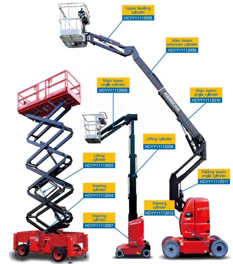
Aerial work platform lift cylinders carry the unique characteristic that their primary failure mode is not an equipment damage event — it is a life safety event. A scissor lift mast cylinder that loses internal pressure integrity while a worker is elevated at 12 metres will cause the platform to descend rapidly, with potentially fatal consequences. This is why AWP lift cylinders are governed by a safety engineering framework that goes far beyond standard hydraulic cylinder specifications.
AWP LIFT CYLINDER SAFETY REQUIREMENTS — BEYOND STANDARD SPECIFICATION
VELOCITY FUSE
A velocity fuse (also called a flow fuse or drop valve) is mandatory in the supply line to every single-acting AWP mast lift cylinder. This device closes automatically if the fluid flow rate exceeds a set threshold — which occurs if the supply hose fails and the platform begins an uncontrolled descent. The velocity fuse must lock before the platform descends more than 150 mm from any elevated position.
PROOF LOAD TEST
EN 280 requires that the complete AWP be proof-load tested at 125% of rated capacity after manufacture and after each major overhaul. The lift cylinder must maintain this load without measurable descent for a minimum test duration. This test is in addition to the standard 1.5× hydrostatic pressure test of the cylinder itself.
LOAD HOLD RATE
AWP standards specify a maximum allowable descent rate under rated load with all control valves in neutral — typically less than 25 mm per 10 minutes from internal piston seal bypass. Any AWP lift cylinder that fails this rate specification must be removed from service immediately — it represents a life safety deficiency, not a productivity issue. The HCYY series aerial work vehicle lift cylinders are manufactured to meet these load-hold rate specifications as a standard production requirement.
第5節
Construction Lift Cylinder Specification by Machine Type
| MACHINE / POSITION | BORE | タイプ | プレッシャー | CRITICAL REQUIREMENT |
|---|---|---|---|---|
| Excavator — boom (5–20 t class) | 100–140 mm | Double-acting | 25–32 MPa | Counterbalance valve, shock absorber port |
| Excavator — bucket (5–20 t) | 80–120 mm | Double-acting | 28~35 MPa | Shock load spec, PU seals, heavy end-cap welds |
| Wheel loader — boom lift | 100–160 mm | Double-acting | 20–28 MPa | Breakout force sizing, load hold |
| Wheel loader — bucket tilt | 80–130 mm | Double-acting | 20–28 MPa | High cycle, piston seal integrity for load hold |
| Scissor AWP — mast lift | 50–100 mm | Single-acting | 16–22 MPa | Velocity fuse, EN 280 compliance, 25mm/10min hold |
| Boom AWP — articulated lift | 63–120 mm | Double-acting | 20–28 MPa | Counterbalance valves, combined load sizing |
| Mobile crane — boom elevation | 120–250 mm | Double-acting | 25–35 MPa | EN 13000 certification, 4:1 safety factor documented |
Sourcing note: The full range of construction equipment hydraulic cylinders — including excavator, loader, crane, and AWP positions across all machine weight classes — is available from the リフトシリンダー product range. For mobile machinery cylinders with documented certification for safety-critical applications, the mobile machinery hydraulic cylinder category provides additional configuration and certification options.
第6条
Site Maintenance for Construction Lift Cylinders
Construction site conditions present the most hostile environment for hydraulic cylinder maintenance — fine silica dust from demolition and earthmoving, diesel exhaust aerosols, lubricant and fuel spillage, and the impact damage from material strikes all act on the exposed rod surface simultaneously. The following site maintenance tasks are essential for maintaining lift cylinder service life in this environment:
Before first operation: visually inspect all exposed rod surfaces — zero tolerance for visible cracks in the chrome, significant scoring, or oil dripping. Wipe exposed excavator and loader cylinder rods with a clean cloth where accessible. Check all hydraulic connections for weeping — any leak on a construction site causes dangerous floor contamination and must be repaired immediately rather than tolerated.
Check boom and arm pivot pins for excessive play — use a pry bar to check lateral and fore-aft movement. More than 3 mm of play in any pin indicates bush wear that is generating side load on the adjacent lift cylinder. Grease all exposed grease nipples. For AWP equipment: perform a load-hold test at maximum rated load — platform must not descend more than 25 mm in 10 minutes.
Hydraulic oil sample for ISO cleanliness analysis — construction site contamination can degrade oil ISO class from 16/14/11 to 19/17/14 in as little as 4 weeks of heavy operation in dusty conditions. If the class exceeds 18/16/13, replace the hydraulic oil and filter immediately rather than waiting for the scheduled change interval. Any lift cylinder with a visible oil rod seal leak must be removed from service and repaired before the next shift.
応募に関するよくある質問
Construction Lift Cylinder Questions
Q01
When an excavator boom cylinder leaks, can I slow the leak with a sealant additive?
No — hydraulic sealant additives are not an appropriate temporary measure for lift cylinder rod seal leaks on construction equipment. These additives typically work by swelling elastomeric seals — which may temporarily reduce the visible leak rate but simultaneously compromises the seal’s designed compression force, contact geometry, and pressure retention at temperature. On an excavator boom cylinder, a leaking rod seal indicates the seal has been mechanically damaged or worn to the point where it can no longer retain full system pressure. Continuing operation with a leaking seal while adding sealant risks catastrophic seal failure during a high-pressure demand cycle, which can cause a rapid, uncontrolled boom descent. The only correct repair is to remove the lift cylinder, disassemble, inspect, and replace the full seal kit along with any rod or bore surfaces that are damaged.
Q02
How often should AWP scissor lift cylinders be formally inspected?
Under EN 280 and most national market regulations, AWP equipment must undergo a formal periodic inspection by a competent person at intervals not exceeding 6 months for rental or high-cycle equipment, and annually for lower-cycle owner-operated equipment. This formal inspection must include a load-hold test at rated capacity, velocity fuse function verification, visual inspection of all structural welds and mounting points, and measurement of platform descent rate under load. The lift cylinder is a primary inspection item — any measured drift rate exceeding 25 mm per 10 minutes at rated load is a mandatory remove-from-service criterion. Records of all inspections must be maintained for the working life of the machine.
Q03
What is the correct way to purge air from an excavator boom lift cylinder after a seal replacement?
After reinstalling an excavator boom lift cylinder following seal replacement, the circuit contains air in the cylinder bore and supply lines that must be purged before the machine is returned to full-load operation. The procedure is: with the machine on a flat surface and the boom supported by a rest, slowly operate the boom up-and-down control several times at low engine speed — this circulates oil through the cylinder and allows air to rise to the reservoir. Top up the hydraulic reservoir to the full mark after each cycle, as air leaving the circuit is replaced by oil. Continue until motion is smooth and no erratic jolting occurs. Then perform a static load test — with a test load of 50% rated payload on the bucket, extend the boom to full height and hold for 5 minutes — any spongy response or unexpected descent indicates air remains in the circuit and the bleeding procedure must be repeated before returning to full excavation duty.
Q04
Can I use a lift cylinder from a smaller machine to temporarily replace a failed cylinder on a larger machine?
This practice is extremely dangerous and must never be done on any lift cylinder serving a safety-critical function — boom, arm, or bucket on an excavator, boom lift on a loader or crane, or any cylinder on an AWP. A smaller-bore cylinder fitted to a larger machine’s circuit will be subjected to system pressure that may exceed its rated working pressure, and at the correct system pressure it will deliver insufficient force — either failing structurally under overload or providing inadequate hold capacity that causes uncontrolled movement of a heavy, potentially lethal load. On non-safety-critical positions — for example, a dozer blade tilt cylinder on a private site with the area cordoned off — a temporary undersized cylinder may be operated at reduced duty (no full-load operation) until the correct replacement arrives, but only with written risk assessment and management approval. For any personnel-carrying or overhead load application, operation with an incorrect lift cylinder is a regulatory violation and creates direct personal liability for the site manager and equipment operator.
CONSTRUCTION LIFT CYLINDER SPECIFICATION SUPPORT
Specifying Lift Cylinders for Your Construction Equipment?
Our engineering team specifies lift cylinders for excavators, loaders, AWPs, and cranes — matched to your machine weight class, system pressure, and safety certification requirements.
編集者: Cxm














