
CIRCUIT DESIGN GUIDE · ACTUATION TYPE · HYDRAULIC LIFT CYLINDERS
Double-Acting vs
Single-Acting
Lift Cylinders — Complete Guide
The choice between single-acting and double-acting lift cylinders is one of the earliest decisions in any hydraulic system design — and it shapes the circuit complexity, energy consumption, pipe count, valve specification, and safety architecture of the entire installation. Both types are the correct answer for different applications. This guide explains the engineering principles that govern the choice, the circuit configurations that each type requires, and the real-world applications where each achieves its best performance.
Flow Requirements
Application Selection
LIFT CYLINDERS · CIRCUIT DESIGN ENGINEERING · JULY 2026
REFERENCE · SINGLE-ACTING vs DOUBLE-ACTING LIFT CYLINDER — KEY DIFFERENCES
PORTS
1 vs 2
Single-acting: one hydraulic port. Double-acting: two ports — cap end and rod end
RETURN FORCE
Gravity vs Hydraulic
Single-acting retracts under gravity or spring; double-acting uses hydraulic pressure for both directions
HOSE COUNT
1 vs 2
Single-acting requires one hydraulic line; double-acting requires two — increases installation cost
CONTROL PRECISION
Lower vs Higher
Double-acting allows metered control in both directions; single-acting lowering depends on load weight
セクション01
How Single-Acting and Double-Acting Lift Cylinders Work
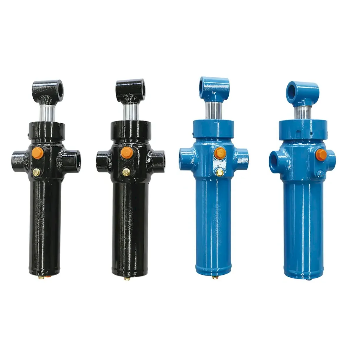
SINGLE-ACTING LIFT CYLINDER
A single-acting lift cylinder has one hydraulic port, feeding the cap-end (blind-end) chamber only. Hydraulic pressure extends the rod; when the control valve returns to neutral and the supply is connected to tank, the rod retracts under the weight of the attached load (gravity return) or a return spring inside the cylinder barrel.
The rod-end chamber breathes freely through an atmospheric vent — this is the port marked with a breather filter on single-acting cylinders. Contamination entering through this breather is a common cause of bore scoring in single-acting lift cylinders used in dusty environments; a sealed breather with a fine filter is mandatory for construction and agricultural single-acting cylinders.
DOUBLE-ACTING LIFT CYLINDER
A double-acting lift cylinder has two hydraulic ports — cap-end and rod-end. Hydraulic pressure applied to the cap-end extends the rod with force equal to the system pressure multiplied by the full bore area. Hydraulic pressure applied to the rod-end retracts the rod with force equal to the system pressure multiplied by the annular area (bore area minus rod area).
Because the retraction force is generated by hydraulic pressure rather than gravity, a double-acting lift cylinder can retract against a load that exceeds its own weight — enabling downward pushing, clamping, and controlled lowering against external resistance. This makes the double-acting type the only viable choice for any application requiring push force in both directions.
セクション02
Circuit Design Differences
The actuation type determines the control valve specification, hose routing, and safety valve requirements for the entire リフトシリンダー circuit. Single-acting and double-acting circuits use different valve types and have different failure mode characteristics:
SINGLE-ACTING LIFT CYLINDER CIRCUIT
CIRCUIT ELEMENTS
▸
3/2 directional control valve (three ports, two positions) or a 4/3 with one port blocked
▸
Single hydraulic supply hose to cap-end port
▸
Atmospheric vent or breather filter on rod-end port
▸
Flow control valve on supply line to limit extension speed
▸
Pilot-operated check or lowering valve for load holding
FAILURE MODE
If the supply hose fails or the control valve jams open-to-tank, the load descends under gravity. Descent speed is limited only by the lowering valve. A correctly sized and set lowering valve prevents runaway descent but cannot prevent descent entirely if the supply is lost — this is the primary safety limitation of single-acting lift cylinders in personnel-carrying applications.
DOUBLE-ACTING LIFT CYLINDER CIRCUIT
CIRCUIT ELEMENTS
▸
4/3 directional control valve (four ports, three positions including neutral)
▸
Two hydraulic hoses — cap-end and rod-end
▸
Flow controls on both lines for speed regulation in each direction
▸
Counterbalance valves on cap-end line for load holding and controlled lowering
▸
Relief valves on both cap-end and rod-end for thermal expansion protection
FAILURE MODE
If the cap-end supply hose fails, the counterbalance valve prevents descent — the load is held in position even with no hydraulic pressure present. This passive load-holding characteristic makes the double-acting type with counterbalance valves the preferred configuration for any lift cylinder supporting personnel or overhead loads where gravity descent must be prevented under all failure conditions.
セクション03
Flow, Speed and Force Calculations
The critical hydraulic calculations differ between the two types — most importantly for the retraction stroke, where a double-acting lift cylinder’s rod-side annular area is smaller than the full bore area:
SINGLE-ACTING — FLOW CALCULATIONS
EXTENSION FLOW (L/min)
Q = A_bore × v_ext × 0.006
A in cm², v in mm/s, constant 0.006 converts units
RETRACTION SPEED
Determined by load weight and lowering valve setting — NOT by pump flow. The pump is not involved in retraction.
EXTENSION FORCE
F = P × π/4 × D²
Full bore area. No rod-end back-pressure in single-acting.
DOUBLE-ACTING — FLOW CALCULATIONS
EXTENSION FLOW (L/min)
Q = A_bore × v_ext × 0.006
Same as single-acting — full bore area on extension
RETRACTION FLOW (L/min)
Q = A_annular × v_ret × 0.006
A_annular = π/4 × (D²−d²) — less than bore area
RETRACTION FORCE
F = P × π/4 × (D²−d²)
Annular area — always less than extension force at same pressure
Speed asymmetry in double-acting circuits: Because the annular area is smaller than the bore area, a double-acting lift cylinder retracts faster than it extends when supplied with the same pump flow rate. For a typical rod-to-bore ratio of 0.6 (rod diameter = 0.6 × bore diameter), the annular area is 64% of the bore area — meaning the cylinder retracts at 1.56× the extension speed with identical pump flow. If equal extension and retraction speeds are required, a regenerative circuit or separate flow controls for each direction must be specified.
第4節
Energy Consumption and Efficiency
The energy efficiency difference between single-acting and double-acting lift cylinders is significant in high-cycle applications and should be quantified when specifying systems with electric motors or battery-powered HPUs:
SINGLE-ACTING
ENERGY
The pump supplies energy only on the extension stroke. On retraction, the load’s potential energy is dissipated through the lowering valve as heat — but no pump energy is consumed. For a lift cylinder completing 100 cycles per hour (50 extensions, 50 retractions), the pump runs at full load only during the 50 extension strokes. The other 50 cycles are free from an energy perspective. This is the energy model for forklift mast cylinders, scissor AWP cylinders, and tipper truck telescopic cylinders.
DOUBLE-ACTING
ENERGY
The pump must supply energy in both directions. For the same 100-cycle example, the pump runs at full load on all 100 strokes — but the retraction stroke consumes less energy than extension because the annular area (receiving oil on retraction) is smaller than the bore area (receiving oil on extension). At a rod-to-bore ratio of 0.6, retraction consumes approximately 64% of the energy of extension per millimetre of stroke. Total energy consumption over the same cycle count is approximately 82% higher than the single-acting equivalent — a meaningful difference in battery-powered mobile equipment and fixed industrial systems with electricity costs.
第5節
Counterbalance and Load-Holding Valves
Both single-acting and double-acting lift cylinders require load-holding valves when they must hold a load in a fixed position for extended periods — but the valve type and its function differs between the two configurations:
PILOT-OPERATED
CHECK (POCV)
Used with single-acting lift cylinders. A POCV allows oil to flow freely into the cylinder (extension) and blocks oil from leaving (prevents retraction) unless a pilot signal is applied. The pilot signal is provided by the directional control valve when the operator selects the lower function. Load is held indefinitely when the operator releases the control — no valve leakage, no drift. The POCV fails safe — if the pilot signal is lost, the load remains held. Installed on the cap-end port, directly at the cylinder if possible to minimise the volume of oil between valve and cylinder that could allow downward drift if the line between the two fails.
COUNTERBALANCE
VALVE (CBV)
Used with double-acting lift cylinders. A counterbalance valve maintains a set back-pressure on the load-bearing side of the cylinder (cap-end for a vertical lifting cylinder), preventing uncontrolled descent if the load side pressure falls. The CBV setting is typically 1.3× the maximum expected load pressure on the cap-end — high enough to hold the load against the cylinder’s own weight and any external downward forces, but low enough that the rod-end operating pressure can pilot it open for controlled lowering. Unlike a POCV, the CBV allows controlled descent even if pilot pressure is lost — the back-pressure it maintains limits the descent rate. For this reason, CBVs are used in mobile equipment where controlled lowering after a circuit failure is preferable to a locked load position.
Both valve types are available integrated into the end-cap of selected models in the リフトシリンダー product range — eliminating the external valve mounting and reducing the number of hydraulic connections between the valve and the cylinder bore.
第6条
Application Selection Guide

| 応用 | タイプ | PRIMARY REASON |
|---|---|---|
| Tipper / dump truck body | Single-acting | Body weight always provides gravity return — single-acting simplifies circuit and reduces hose count |
| Forklift mast — free-lift and main lift | Single-acting | Fork carriage weight provides gravity return — simpler circuit, lower energy consumption per cycle |
| Forklift tilt cylinder | Double-acting | Must push in both forward and rearward tilt directions — gravity cannot provide forward tilt force |
| Scissor AWP mast | Single-acting | Platform weight provides gravity return; POCV and velocity fuse provide safety load-holding |
| Excavator boom / arm | Double-acting | Must push both into and out of ground; precise position control in both directions; load on the cylinder can act in either direction depending on working angle |
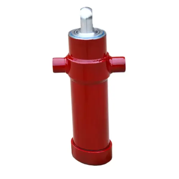
| Front-top tipper cylinder | Single-acting | Body returns under gravity; telescopic cylinder simplifies to one port; circuit is very simple |
| Agricultural tractor 3-point hitch | Single-acting | Implement weight provides gravity lowering; tractor hydraulic system uses simple open-centre spool valve |
| Industrial scissor table (push-down needed) | Double-acting | When active downward force is required — pressing, clamping, or pushing against a load on the return stroke |
Both single-acting and double-acting types are available across the full bore range in the リフトシリンダー product range. Mobile machinery lift cylinder configurations — including telescopic single-acting for tipper bodies — are available from the mobile machinery hydraulic cylinder category with circuit design notes and valve integration options on request.
応募に関するよくある質問
Actuation Type Questions
Q01
Can a single-acting lift cylinder be converted to double-acting by adding a second port?
In most cases, no — not without significant machining. A single-acting lift cylinder has a sealed rod-end cap with an atmospheric breather; to convert it to double-acting, the rod-end cap must be machined to accept a hydraulic port, the breather must be removed and the resulting opening sealed or repurposed as the port, and the rod-end cap-to-barrel seal must be upgraded from a static O-ring (adequate for atmospheric pressure) to a dynamic seal rated for full hydraulic pressure. Additionally, the piston seal, which on a single-acting cylinder is typically a single-lipped seal designed to hold oil on the cap-end side only, must be replaced with a double-lipped piston seal capable of holding pressure from both sides. The cost of these modifications typically approaches or exceeds the cost of replacing the lift cylinder with a correct double-acting specification — making conversion economically unviable for standard bore sizes available from stock.
Q02
Why does my double-acting lift cylinder retract faster than it extends even though I set the same flow control on both lines?
This is correct and expected behaviour, not a fault. Because the rod-end annular area is smaller than the full bore area, the same volume of oil entering the rod-end produces a greater linear rod velocity than the same volume entering the cap-end. A flow control valve set to the same setting in both directions passes the same volume flow rate — but the smaller area converts that volume into greater velocity on retraction. To achieve equal extension and retraction speeds, the rod-end flow control must be set to a lower flow rate than the cap-end control, in the ratio of annular area to bore area. For a cylinder with a bore of 100 mm and a rod of 60 mm, the ratio is: π/4×(100²−60²) / π/4×100² = 6 400/10 000 = 0.64 — so the rod-end flow control must be set to 64% of the cap-end flow control setting to achieve equal speeds in both directions.
Q03
What is a regenerative circuit and when is it used with a double-acting lift cylinder?
A regenerative circuit connects the rod-end port of a double-acting lift cylinder back to the cap-end supply line, so that the oil expelled from the rod-end during extension is added to the pump flow entering the cap-end. This increases the effective extension speed beyond what the pump alone can provide, at the cost of a reduction in available extension force. The extension speed in regenerative mode equals pump flow divided by rod area alone (not bore area), which can be 2–4× the standard extension speed for typical rod-to-bore ratios. The force available in regenerative mode is reduced to pressure multiplied by rod cross-sectional area (rod only, not annular area). Regenerative circuits are used on horizontal cylinder applications where rapid extension speed is more important than maximum force, and where the load is light enough to be moved by the reduced regenerative force. They are not suitable for vertical lifting applications where the full bore-area force is needed to overcome gravity — a regenerative circuit on a vertical lift cylinder would reduce the available lifting force to the point where the cylinder cannot support rated load during extension.
Q04
Is a single-acting or double-acting lift cylinder better for a vertical platform where personnel work at height?
Both types are used for personnel platforms, but with different safety architectures. Single-acting lift cylinders dominate in scissor AWPs because the circuit is simpler and the gravity-return characteristic is predictable — the platform always descends when hydraulic supply is removed, which the POCV and velocity fuse prevent from becoming uncontrolled. Double-acting lift cylinders are used in articulated boom AWPs and some mast-type platforms where the boom geometry means gravity alone cannot reliably lower the platform from all positions — the rod-end pressure is needed to push the platform down in some geometries. Regardless of actuation type, every personnel-carrying platform lift cylinder must have a load-holding valve mounted directly at the cylinder port to prevent descent if the hose between valve and cylinder fails, and must meet the platform descent rate specification of the applicable standard (typically EN 280 for scissor lifts, EN 13000 for crane-type platforms). The actuation type choice does not replace this safety valve requirement — it is an additional requirement that applies to both.
LIFT CYLINDER CIRCUIT DESIGN SUPPORT
Choosing the Right Actuation Type for Your Application?
Our application engineers confirm the correct actuation type, valve specification, and circuit design for any lift cylinder application — from simple single-acting industrial platforms to complex double-acting mobile machinery installations.
編集者: Cxm














