
APPLICATION GUIDE · DOCK & LOGISTICS · HYDRAULIC LIFT CYLINDERS
Dock Leveller
Hydraulic Lift Cylinders
Platform · Lip · Ramp
The hydraulic dock leveller is one of the most heavily cycled pieces of fixed industrial equipment in any distribution centre or logistics facility — a high-throughput warehouse dock can complete 80–120 truck loading cycles per day, with the platform lift cylinder operating at each cycle. Despite this intensity, the dock leveller lift cylinder is often the most neglected hydraulic component in a building, maintained only when it fails rather than on a structured preventive schedule. This guide covers specification, load calculations, corrosion protection, and the maintenance programme that keeps dock leveller lift cylinders in service for 10–15 year intervals between rebuilds.
Lip Extension
Load-Hold Safety
LIFT CYLINDERS · DOCK LEVELLER APPLICATION · JULY 2026
REFERENCE · DOCK LEVELLER LIFT CYLINDER PARAMETERS
PLATFORM BORE
80–160 mm
Single-acting plunger or double-acting; capacity 6–12 t platform + load rated
DAILY CYCLES
40–120
High-throughput distribution docks — lift cylinder accumulates 15 000–40 000 cycles per year
PRESSIONE DEL SISTEMA
16–20 MPa
Dock levellers typically use compact HPU units at 16–20 MPa with single-acting platform cylinders
LOAD HOLD
Full shift
Platform must hold rated load for the full truck loading period — typically 15–45 minutes per cycle
SEZIONE 01
Dock Leveller Types and Hydraulic Cylinder Positions
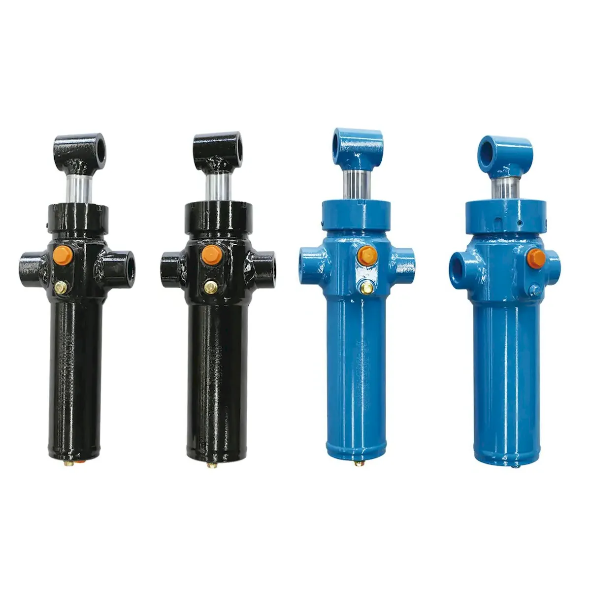
Hydraulic dock levellers use two or three cylinder positions depending on the design configuration. Understanding which position each cylinder serves is the starting point for correct replacement specification:
PLATFORM
LIFT
The main lift cylinder raises the entire leveller deck from its stored (flush with dock floor) position upward, typically 300–450 mm above dock floor level, to allow height adjustment to match the truck bed. Single-acting plunger or double-acting depending on the leveller design — single-acting models lower under the deck’s own weight (gravity return); double-acting models use hydraulic pressure for controlled lowering. Bore: 80–160 mm. The platform lift cylinder is the structural heart of the dock leveller hydraulic system and must hold the combined weight of the platform and any forklift truck on it for the duration of loading.
LIP
EXTENSION
A smaller double-acting or spring-extended cylinder that pivots the front lip of the leveller platform outward and downward to rest on the truck floor, bridging the gap between the dock and the truck. Bore: 40–80 mm. Stroke: 100–250 mm depending on lip arc. The lip extension lift cylinder must deploy the lip against its own weight at any platform height within the leveller’s adjustment range, which means it must generate sufficient torque to rotate the lip through its full angular arc even at the minimum and maximum platform height positions.
VEHICLE
RAMP
On edge-of-dock levellers, a vehicle ramp cylinder lowers a short ramp section to the truck floor independently of the main platform. Also found on yard ramps and mobile dock ramp equipment. Typically single-acting with spring return, bore 50–100 mm. On vehicle restraint docks, this cylinder position also controls the truck wheel chock engagement — a safety-critical function requiring counterbalance valve load-holding when the restraint is engaged.
SEZIONE 02
Platform Lift Cylinder — Force and Stroke Sizing
The platform lift cylinder must raise the dock leveller deck against three simultaneous loads: the dead weight of the steel deck structure, any static load on the deck at the moment of lift initiation, and the geometric force required by the pivot arrangement of the platform. Because the platform pivots on a rear hinge rather than lifting vertically, the lift cylinder — which is typically mounted below the platform at an angle — must generate more force than the simple vertical load would suggest:
TYPICAL SIZING PARAMETERS — 6 t RATED DOCK LEVELLER
STROKE DETERMINATION
The stroke of the dock leveller platform lift cylinder is determined by the total height adjustment range of the leveller — typically ±300 mm from dock floor level (300 mm above for high trucks, 300 mm below for low trucks). However, because the cylinder is mounted at an angle under the platform, the cylinder stroke is longer than the vertical travel — typically 1.3–1.8× the vertical travel, depending on the cylinder mounting angle and the arm length to the rear hinge.
For a 600 mm total height adjustment range with a cylinder mounting angle of 35° from horizontal and a 900 mm arm moment: required stroke ≈ 600 / sin(35°) = 600 / 0.574 ≈ 1 045 mm. Select the next standard stroke above this value — in this case 1 100 mm.
SEZIONE 03
Lip Extension Cylinder — Angle and Speed Requirements
The lip extension lift cylinder rotates the front lip through approximately 90–110° from its stored (folded-under) position to its extended (resting on truck floor) position. The force required varies significantly through this arc — maximum force is required at the start of extension when the lip is horizontal and its full weight acts as a moment against the cylinder, and minimum force is needed at full extension when gravity assists the final lowering:
FORCE PROFILE
At initial extension (0–20° lip angle from stored position): the full weight of the lip acts against the cylinder through the worst-case moment arm. For a 250 kg lip section with a 600 mm moment arm to the pivot: torque = 250 × 9.81 × 0.6 = 1 473 Nm. At a cylinder mounting radius of 200 mm, the required cylinder force = 1 473 / 0.2 = 7 365 N. A 50 mm bore lift cylinder at 16 MPa delivers 31.4 kN — adequate with substantial margin. Size for the initial extension force, not the mean-stroke force.
EXTENSION SPEED
Lip extension speed must be controlled to prevent the lip dropping onto the truck floor at high velocity — impact at the truck floor can damage the truck bed, injure feet, and stress the lip hinge. A flow control valve in the lip extension supply limits maximum extension speed to approximately 30–60°/second of lip arc. The lift cylinder must complete the full extension in 3–6 seconds from operator command, which requires a minimum flow rate determined by the bore area and stroke length to be covered per second.
LIP RETRACTION
On double-acting lip cylinders, retraction raises the lip back to the stored position before the platform can lower to floor level — the control circuit must sequence platform lowering after lip retraction is confirmed. On spring-return lip designs, the spring provides the retraction force; verify that the spring rate is matched to the cylinder’s retraction-stroke back-pressure to prevent the spring from fighting the cylinder during the lowering phase.
SEZIONE 04
Load-Holding Safety and Fail-Safe Requirements
The dock leveller platform lift cylinder must hold the platform — with a loaded forklift truck on it — at the set height for the duration of the truck loading operation. If the platform descends during loading, the gap between the platform lip and the truck floor can trap a pallet edge or forklift wheel, causing a tip-over incident. The load-holding requirements for dock leveller lift cylinders are therefore safety-critical:
PILOT-OPERATED CHECK
Every dock leveller platform lift cylinder must have a pilot-operated check valve (POCV) mounted directly at the cylinder cap-end port. The POCV blocks oil from leaving the cylinder unless a deliberate lowering signal is applied. With the POCV in place, pump failure, hose rupture, or control valve failure cannot cause the platform to descend — the load is held indefinitely by the trapped oil column. Maximum permitted drift rate under rated load: 5 mm per 10 minutes according to EN 1570 (lifting tables) requirements applicable to dock levellers.
PRESSURE DROP ALARM
Modern dock management systems monitor the platform lift cylinder pressure continuously during loading. A pressure drop below a set threshold — indicating platform descent or hydraulic circuit failure — triggers an alarm and automatically activates the vehicle restraint system to lock the truck in position. This dual-safety architecture (POCV plus pressure monitoring) is increasingly specified for dock levellers in facilities processing hazardous goods or operating with high forklift traffic density.
MECHANICAL SAFETY LEG
High-safety dock installations add a mechanical safety leg — a positive mechanical stop that engages automatically when the platform is raised to the working position and prevents descent even if all hydraulic containment fails. The lift cylinder lowers onto the safety leg before loading commences; the leg is retracted hydraulically before the platform can be lowered at end of loading. The safety leg provides protection independent of the lift cylinder’s hydraulic integrity.
Dock leveller lift cylinders in facilities subject to the EU Machinery Directive (2006/42/EC) must have documented evidence of the load-holding valve specification, test pressure, and drift rate — the POCV function must be verified at commissioning and at each annual inspection. For industrial-grade dock leveller lift cylinders with integrated POCV port options, the cilindro idraulico per ingegneria industriale range provides configurations with the applicable valve integration and documentation packages.
SEZIONE 05
Corrosion Protection for Dock Environments
The dock pit — the recessed area below the leveller platform — is one of the most corrosive environments for a fixed installation hydraulic cylinder. Road salt deposited by truck tyres, pooled rainwater from dock ingress, and cleaning chemicals from dock hygiene programmes all act on the lift cylinder’s outer surfaces and exposed rod. Corrosion protection must be specified as a deliberate engineering decision, not as an afterthought:
OUTER BODY
COATING
The cylinder barrel and end-caps must be coated with a corrosion-resistant system rated to a minimum of 480 hours salt spray (ISO 9227) — at least twice the standard 200-hour industrial coating specification. A zinc-epoxy primer plus two-coat high-build polyurethane topcoat at a minimum total dry-film thickness of 200 μm achieves this requirement. The coating must extend over all weld seams and transition zones between barrel and end-caps, which are the first areas where corrosion initiates.
ROD SURFACE
PROTECTION
The platform lift cylinder rod is exposed to the dock pit atmosphere every time the platform is raised and then retracted. Standard hard chrome (25–35 μm) provides adequate corrosion resistance for inland docks in temperate climates. For coastal locations, cold-climate facilities with heavy road salt use, or food distribution docks with acidic cleaning chemical washdown, upgrade to stainless steel rod (316L) or HVOF rod coating — both provide significantly better corrosion resistance than chrome in chemically aggressive dock environments.
WIPER
PROTECTION
Road salt crystals carried on the platform lift cylinder rod are small enough to pass a standard rubber wiper and reach the rod seal. A metal scraper ring at the outermost position of the gland removes the solid salt crystals before they can abrade the rod seal — this is the same wiper upgrade specified for refuse vehicle packing blade cylinders and for the same reason: solid particle exclusion before it reaches the elastomeric sealing elements.
SEZIONE 06
Maintenance Schedule for Dock Leveller Cylinders
The dock leveller lift cylinder is typically installed and forgotten until it fails — partly because the cylinder is concealed in the dock pit and not visible during normal operation, and partly because dock leveller hydraulic maintenance is often not included in any facility’s regular maintenance programme. A structured preventive schedule dramatically extends cylinder service life and avoids the unplanned dock downtime that disrupts inbound and outbound logistics operations:
MONTHLY
Inspect the platform lift cylinder rod for oil weeping at the gland — any oil visible on the rod at the dock pit floor level indicates the rod seal is passing its service life. Check the hydraulic reservoir level in the HPU unit. Verify that the platform holds its set height for a 5-minute static test with a loaded forklift on it — platform descent greater than 10 mm in 5 minutes requires immediate cylinder inspection.
TRIMESTRALE
Clean the dock pit and lift cylinder outer surfaces with a pressure washer — remove accumulated road salt and organic debris from all surfaces. Apply corrosion-preventive wax to all exposed steel and the cylinder rod after cleaning. Verify the POCV function: raise platform to working height, shut off the HPU power, and check that the platform holds position for 10 minutes with rated load. Replace the HPU hydraulic filter element.
ANNUALLY
Replace hydraulic oil and filter in HPU unit. Replace lift cylinder rod seal kit (gland seals, wiper, metal scraper) as preventive action on docks operating more than 40 cycles per day. Inspect cylinder outer coating for rust blistering or mechanical damage from dock pit debris — touch up any bare metal areas immediately. Check all port connection torques and re-torque any fittings that have moved. Inspect lip cylinder for rod scoring from road debris contact during extension.
5 YEARS
Full lift cylinder inspection: remove from dock pit, full disassembly, bore inspection, rod chrome thickness measurement, and pressure test at 1.5× working pressure. Any rod below 15 μm chrome thickness should be re-chromed or the cylinder replaced. This 5-year inspection typically identifies whether the cylinder can continue in service for another 5-year period or requires rebuilding — a dock leveller platform lift cylinder in a clean, well-maintained installation should readily achieve a 10–15 year service life between complete overhauls.
Replacement dock leveller platform lift cylinders and lip extension cylinders — dimensionally matched to all major dock equipment brands including Assa Abloy, Hormann, Stertil-Koni, and Loading Systems — are available from the cilindro di sollevamento product range. Provide the dock leveller brand, model, and serial number, along with the existing cylinder bore, stroke, and port thread specification, to ensure a dimensionally identical replacement is supplied.
DOMANDE FREQUENTI SULL'APPLICAZIONE
Dock Leveller Cylinder Questions
Q 01
Our dock leveller platform is slowly sinking during truck loading — the rod seal was replaced last month. What else could cause this?
Platform descent after a recent rod seal replacement almost always indicates that the piston seal — not the rod seal — is the primary leakage path. The piston seal in a dock leveller platform lift cylinder allows oil to bypass from the cap-end to the rod-end of the cylinder internally, causing the platform to slowly sink even though there is no visible external oil leak at the gland. To confirm: raise the platform to working height, close the control valve, and measure platform position every 2 minutes for 10 minutes. If the platform descends continuously without any visible oil at the gland, the piston seal is bypassing. The repair requires full cylinder disassembly, piston seal replacement, and a post-rebuild pressure test before reinstallation. If the dock leveller uses a single-acting plunger cylinder (no piston), then platform drift is caused by the POCV allowing small internal bypass — the POCV itself requires inspection and possibly replacement.
Q 02
The dock leveller platform rises but the lip does not extend — what should I check first?
A platform that rises normally but a lip that does not extend indicates either an electrical issue (the lip solenoid valve is not energising) or a hydraulic flow problem specific to the lip circuit. Check the solenoid valve operation first — hold the lip extension button and listen for the solenoid click, or check the valve voltage with a multimeter. If the solenoid is energising, check the hydraulic flow to the lip lift cylinder by disconnecting the cap-end hose and operating the lip button — if oil flows from the disconnected port, the problem is in the lip cylinder itself (stuck rod, collapsed seal, frozen piston). If no oil flows even with the solenoid energised and pump running, the lip circuit flow control valve may be fully closed, a hose may be kinked or disconnected internally, or the directional valve spool may be seized. The lip extension cylinder is typically the smallest and simplest hydraulic cylinder in the dock leveller system — if it is not moving with correct pressure applied, the most likely cause is a seized rod from corrosion during a period when the dock was not used regularly.
Q 03
Can a dock leveller lift cylinder be replaced with a cylinder of a different bore to increase the leveller’s load capacity?
Not without a complete structural review of the dock leveller. Increasing the lift cylinder bore to generate more force allows heavier forklift trucks on the leveller, but the leveller’s steel platform structure, lip hinge, and pit frame were all designed for the original rated capacity. The increased load would stress these components beyond their design limits. Additionally, the HPU unit (pump, motor, and reservoir) must be capable of supplying the higher flow required by the larger bore cylinder at the same system pressure — if it is not, the larger lift cylinder will extend and retract more slowly than the original. The correct process for increasing a dock leveller’s rated capacity is to contact the dock leveller manufacturer and request a formal capacity upgrade — which may involve replacing the entire leveller or at minimum upgrading the structural components along with the hydraulic cylinders.
Q 04
How should we specify a dock leveller lift cylinder replacement for a cold storage facility where dock pits reach −18°C?
A dock leveller lift cylinder in a −18°C cold store dock pit requires three modifications from standard specification. First, the hydraulic oil in the HPU must be a low-temperature grade — ISO 32 HV with a pour point below −35°C — to remain pumpable at cold store ambient temperature. Standard ISO 46 oil becomes highly viscous at −18°C and stresses the HPU pump seals. Second, the lift cylinder rod seal must be specified in Arctic-grade polyurethane or FKM (Viton) rated to −40°C — standard NBR seals become brittle and crack at cold store temperatures, causing immediate failure when the seal is dynamically loaded on the first extension stroke of the shift. Third, the POCV should be verified for correct function at low temperature — some POCV designs use elastomeric seats that stiffen at −18°C and can either stick open (allowing drift) or refuse to open (preventing platform lowering) at extreme cold. Specify a POCV with a PTFE seat or an all-metal seat and spring for cold store dock leveller lift cylinder installations.
DOCK LEVELLER LIFT CYLINDER SUPPLY
Replacing a Dock Leveller Lift Cylinder?
Send us the dock leveller brand and model, the existing cylinder bore, stroke, and port thread, and our team will supply a dimensionally matched replacement cilindro di sollevamento with the correct corrosion protection and seal specification for your dock environment.
Redattore: Cxm














