
Agricultural Engineering Series · Volume II
Advanced Engineering of
Main & Auxiliary Lifting Cylinders
in No-Tillage Machines
Conservation agriculture relies heavily on the physical force required to slice through undisturbed soil and dense crop residue. This comprehensive engineering guide delves deeply into the kinematics, fluid power dynamics, and extreme-environment tribology of the hybrid electro-hydraulic actuators that power modern zero-till planters and seeders.
Agronomic Kinematics
Agricultural Tribology
01. The Agronomic Physics of Conservation Tillage
Traditional agriculture utilizes heavy plows to aggressively turn over the topsoil, effectively burying previous crop residue, disrupting weed root systems, and heavily aerating the earth. While this creates a soft seedbed, it leads to severe soil erosion, massive moisture evaporation, and the destruction of the natural soil biome. The global shift toward No-Tillage (Zero-Till) farming eliminates the plow entirely. Instead, seeds are planted directly into unplowed, residue-covered soil.
From a mechanical engineering perspective, this agronomic shift presents a monumental challenge in fluid power dynamics. Without the soil being pre-softened by a plow, the row units on a planter must possess immense vertical cutting force to slice through tough, fibrous root systems (such as corn stalks or wheat stubble) and penetrate the highly compacted earth. Standard hydraulic lift cylinders designed merely for lifting weight are inadequate for this application. The machinery requires sophisticated, high-speed actuators capable of generating dynamic, variable downforce while simultaneously providing rapid shock absorption.
The Downforce Equation in Planter Kinematics
To achieve perfect seed placement—the most critical factor in crop yield—a planter’s disc opener must maintain a mathematically precise depth. The total required downforce must exceed the sum of two resisting forces: the physical resistance of the soil penetration and the upward lifting force generated by the forward velocity of the tractor. If the downforce is too low, the seed is planted too shallow, leading to poor germination and bird predation. If the downforce is too high, the gauge wheels create severe “sidewall compaction,” crushing the soil structure so heavily that seedling roots cannot penetrate it laterally.
Consequently, the actuator must not just push down with maximum force; it must modulate that force flawlessly in real-time, often adjusting hundreds of times per second as the planter transverses changing soil types (e.g., transitioning from loose sandy loam to dense clay).
02. Anatomy of the Main & Auxiliary Lifting Spring Cylinder
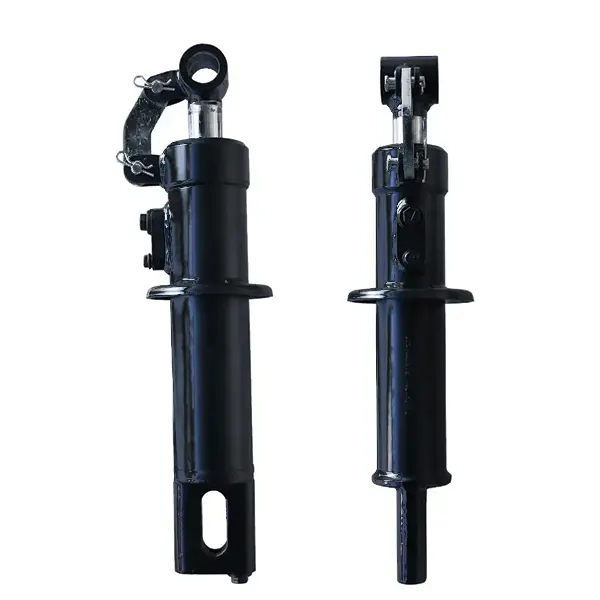
To solve the downforce paradox, engineers developed a highly specialized hybrid actuator. These cylinders combine the absolute holding power of hydraulic fluid with the rapid kinetic response of heavy-duty mechanical coil springs. This dual-architecture is fundamentally different from standard industrial actuators.
🗜️ The Mechanical Spring Element
Constructed from high-tensile Silicon-Manganese spring steel (60Si2Mn), the massive external or internal coil spring provides the baseline mechanical downforce. As the tractor drags the implement, this spring remains under constant compression, transferring kinetic energy continuously to the cutting coulters. Its primary advantage is speed; when the row unit hits a subterranean rock, the mechanical spring compresses instantly (at the speed of sound through steel), absorbing the shock without waiting for hydraulic fluid to route through relief valves.
💧 The Hydraulic Actuation Element
The hydraulic cylinder running through the core of the spring serves two distinct purposes. First, it acts as a dynamic tensioner. By modulating hydraulic pressure via the tractor’s ECU, the operator can actively compress or decompress the spring on-the-fly, adjusting the baseline downforce from the tractor cab. Second, at the end of the field (the headlands), the hydraulic remote reverses flow, commanding the cylinder to overcome the spring entirely and rapidly retract, lifting the heavy row unit out of the earth for turning maneuvers.
03. Hydraulic Circuit Integration: Active vs. Passive Control
The integration of these auxiliary lifting cylinders with the tractor’s main hydraulic system defines the implement’s accuracy. Most legacy agricultural equipment utilized “Passive” downforce systems. The operator would manually set a pressure reducing valve at the tractor remote to apply a static 1,000 lbs of hydraulic force. While simple, this static force cannot account for the dynamic changes in a field. When crossing a soft patch of soil, the static 1,000 lbs would suddenly become excessive, burying the seeds too deep.

The Rise of Active Electro-Hydraulic Downforce
Modern precision agriculture demands “Active” downforce. This system utilizes a sophisticated Closed-Center Load Sensing (CCLS) hydraulic circuit in tandem with electronic load cells (weigh pins) installed directly on the planter’s gauge wheels.
- 1
Data Acquisition
As the planter moves, the gauge wheel load cells measure exactly how much residual weight is resting on the soil surface at a rate of over 200 times per second. If the soil softens, the gauge wheel sinks slightly, and the measured load drops.
- 2
Proportional Valve Modulation
This data is instantly fed to the implement’s ECU. The ECU commands a highly responsive Pulse Width Modulated (PWM) proportional pressure reducing/relieving valve (PRRV). The PRRV instantly adjusts the fluid pressure sent to the lift cylinder’s cap end.
- 3
Hydraulic Accumulator Damping
Because hydraulic fluid is incompressible, sudden violent impacts would rupture the hoses before the valve could react. Nitrogen-charged diaphragm accumulators are plumbed in parallel with the cylinders. These accumulators act as hydraulic shock absorbers, instantly taking in high-pressure fluid spikes during rapid rod compression, ensuring the structural survival of the entire fluid power circuit.
04. Environmental Metallurgy and Agricultural Tribology
Agricultural environments are profoundly destructive to mechanical actuators. A no-till planter operates in a cloud of highly abrasive silicate dust (soil), corrosive anhydrous ammonia or liquid nitrogen fertilizers, and extreme moisture. Consequently, standard industrial cylinders fail rapidly in this environment. The design of these agricultural cylinders requires uncompromising material science.
🧪 Advanced Surface Treatments
The piston rods must possess both immense tensile strength to resist buckling under the heavy spring compression, and a glass-hard outer shell to prevent scoring from rocks and debris. Engineers utilize medium-carbon steels like C45E or 42CrMo4, which are subjected to localized induction hardening prior to plating. This creates a rod with a ductile, shatter-resistant core, wrapped in an HRC 55+ hardened outer layer.
Following heat treatment, the rods receive a heavy electro-deposition of hard chrome. For agricultural specifications, this plating must be substantially thicker than standard indoor industrial units—often exceeding 30 microns—and must routinely pass 120-hour Neutral Salt Spray (NSS) corrosion testing to guarantee survival against liquid fertilizer splash.
Defeating Contamination: The Dual-Lip Scraper
The ultimate failure point of any agricultural cylinder is the rod gland (the end cap where the rod extends and retracts). If dust breaches this point, it turns the hydraulic oil into a grinding paste, obliterating the internal piston seals within hours. To prevent this, premium no-till cylinders utilize heavily reinforced Polyurethane (PU) double-lip wiper seals. The aggressive outer lip is designed like a rigid chisel, physically scraping dried mud and corn-stalk residue off the retracting rod. The softer inner lip acts as a secondary defense, capturing microscopic dust particles and preventing residual hydraulic oil weeping.
05. Expert Diagnostics and Lifecycle Management
During the brief, intense planting season, agricultural machinery must operate 24/7. Downtime is economically catastrophic. Consequently, maintenance managers and equipment operators must employ rapid, highly accurate diagnostic protocols to identify hydraulic anomalies before they escalate into catastrophic system-wide failures.
Symptom: Uneven Planting Depth
If the tractor operator notices certain row units failing to penetrate the soil, resulting in seeds resting on the surface, the immediate suspect is internal seal bypass within the auxiliary lift cylinder. To diagnose: with the machine safely supported on jack stands and the engine off, disconnect the return hydraulic line from the suspect cylinder. Command the tractor to apply downforce pressure to the extend port. If a steady stream of fluid ejects from the open return port, the internal piston seal is completely destroyed, allowing fluid to bypass without generating force. Immediate resealing or replacement is required.
Symptom: Spongy or Jerky Retraction
When lifting the planter at the headlands, if the cylinders retract in a jerky, shuddering motion, it indicates severe aeration (air trapped in the hydraulic lines). Because air compresses under pressure (while oil does not), the trapped air acts like a chaotic spring, causing the cylinder to bounce. This is often caused by a microscopic suction leak on the pump inlet side, or extremely low hydraulic fluid levels in the tractor reservoir causing the pump to ingest air on steep inclines. The system must be fully bled of air following the manufacturer’s venting procedure.
To ensure maximum operational lifespan across massive commercial farms, agricultural engineers recommend adhering rigorously to the ISO 4406 fluid cleanliness standard. Maintaining hydraulic oil at a cleanliness code of 18/16/13 through dedicated return filtration dramatically reduces the abrasive wear on the cylinder’s internal bore and the tractor’s expensive proportional control valves.
06. Strategic Procurement for Mobile Machinery
Upgrading legacy agricultural fleets to modern active downforce systems is one of the highest ROI investments in modern farming, directly correlating to increased crop yields through precision seed placement. When agricultural cooperatives and heavy machinery manufacturers source components, they must look beyond standard off-the-shelf industrial actuators.
Properly specifying mobile machinery hydraulic cylinders ensures that the actuators are purpose-built for the shock loads, extreme temperature fluctuations, and severe chemical exposure inherent to off-highway applications. Replacing failing standard cylinders with these ruggedized, spring-integrated agricultural units guarantees the mechanical reliability required to conquer the short, critical windows of the planting season.
Revolutionize Your Agricultural Operations
Maximize crop yields and completely eliminate seedbed inconsistencies. Explore our catalog of precision-engineered, rigorous-tested hybrid spring-assist cylinders designed specifically for the extreme conditions of no-tillage farming.














