
MEWP Engineering Series · Volume I
Hydraulic Lift Cylinders
for Aerial Work Platforms
Mobile Elevating Work Platforms (MEWPs) represent the intersection of heavy-duty lifting capability and uncompromising human safety. This comprehensive mechanical engineering guide dissects the fluid dynamics, kinematics, tribology, and rigorous safety protocols embedded within the hydraulic actuators that elevate scissor lifts, articulating booms, and telescopic work platforms to extreme altitudes.
Scissor Lift Kinematics
Load Holding Valves
01. The Criticality of Fluid Power in Mobile Elevating Work Platforms
The aerial work platform (AWP) industry is governed by some of the most stringent regulatory standards in the global heavy machinery sector, notably ANSI A92 in North America and EN 280 in Europe. Unlike earthmoving equipment, where a hydraulic failure might result in a dropped load of dirt, a catastrophic hydraulic failure in a MEWP directly threatens human life. Consequently, the hydraulic lift cylinders utilized in these machines are engineered with safety factors and redundancies that far exceed standard industrial applications.
Fluid power provides the unmatched power density required to lift heavy steel boom structures and occupied platforms up to 180 feet (55 meters) into the air, while maintaining a vehicle footprint small enough to navigate construction sites or warehouse aisles. The actuators must perform flawlessly under wildly varying conditions: from the freezing winds of a high-altitude winter construction site causing hydraulic fluid viscosity to spike, to the blistering heat of a summer tarmac that thins the oil and tests the thermal limits of the elastomeric seals.
Furthermore, these cylinders are subjected to complex, multi-directional stress vectors. Wind loads on an elevated platform create immense side-loading forces that travel down the boom and translate into radial forces on the cylinder’s rod and internal wear bands. Designing a cylinder to withstand these dynamic moments requires advanced finite element analysis (FEA) and an uncompromising approach to metallurgical selection and seal tribology.
02. Scissor Lift Cylinders: The Mathematics of Force Multiplication
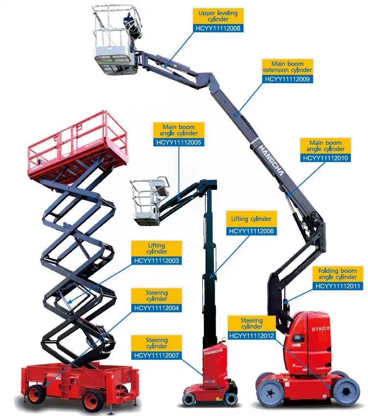
Scissor lifts rely on a pantograph mechanism to achieve vertical elevation. While the mechanical design allows for a large platform area and high lifting capacities, the kinematics present a brutal challenge for the hydraulic lift cylinder. The mechanical advantage (or rather, disadvantage) of a scissor mechanism is highly non-linear.
The “Breakaway” Force Paradox
When a scissor lift is fully collapsed (stowed position), the angle between the scissor arms and the horizontal plane is extremely small (often less than 10 degrees). Because the lift cylinder is usually mounted horizontally or at a very shallow angle to push the arms apart, the thrust required to initiate the lift—known as the breakaway force—is exponentially higher than the force required when the lift is fully extended. Mathematically, the required cylinder force approaches infinity as the stack angle approaches zero. To overcome this, engineers must utilize large-bore cylinders to generate massive force at normal system pressures (e.g., 200 bar), or implement clever offset mounting geometries that increase the initial lever arm.
As the scissor lift elevates and the angle of the arms increases, the required lifting force drops dramatically. However, the hydraulic flow rate required to maintain a constant upward velocity increases. This inverse relationship means the cylinder must be robust enough to handle extreme pressure spikes at the bottom of the stroke, while possessing internal porting large enough to handle high fluid flow velocities at the top of the stroke without inducing fluid cavitation or excessive heat generation.
Furthermore, scissor lift cylinders often function as the primary structural stop when the machine lowers. As the scissor stack collapses, the cylinder retracts completely. To prevent the heavy steel arms from slamming into the chassis and creating dangerous pinch points or shock loads, the cylinders are equipped with sophisticated internal rod-end cushions. These cushions act as hydraulic shock absorbers, restricting fluid escape in the final few inches of travel, gently decelerating the massive weight to a soft, controlled stop.
03. Boom Lifts: Articulating, Telescopic, and Leveling Cylinders
Boom lifts present a completely different set of engineering challenges compared to scissor lifts. In an articulating or telescopic boom lift, the main lift cylinder operates as a massive structural lever. It is pinned between the rotating turntable and the primary boom section. The load moment on this cylinder is calculated by multiplying the total weight of the boom, platform, and payload by the horizontal distance from the boom’s pivot point to the combined center of gravity.
Main Elevation Cylinders
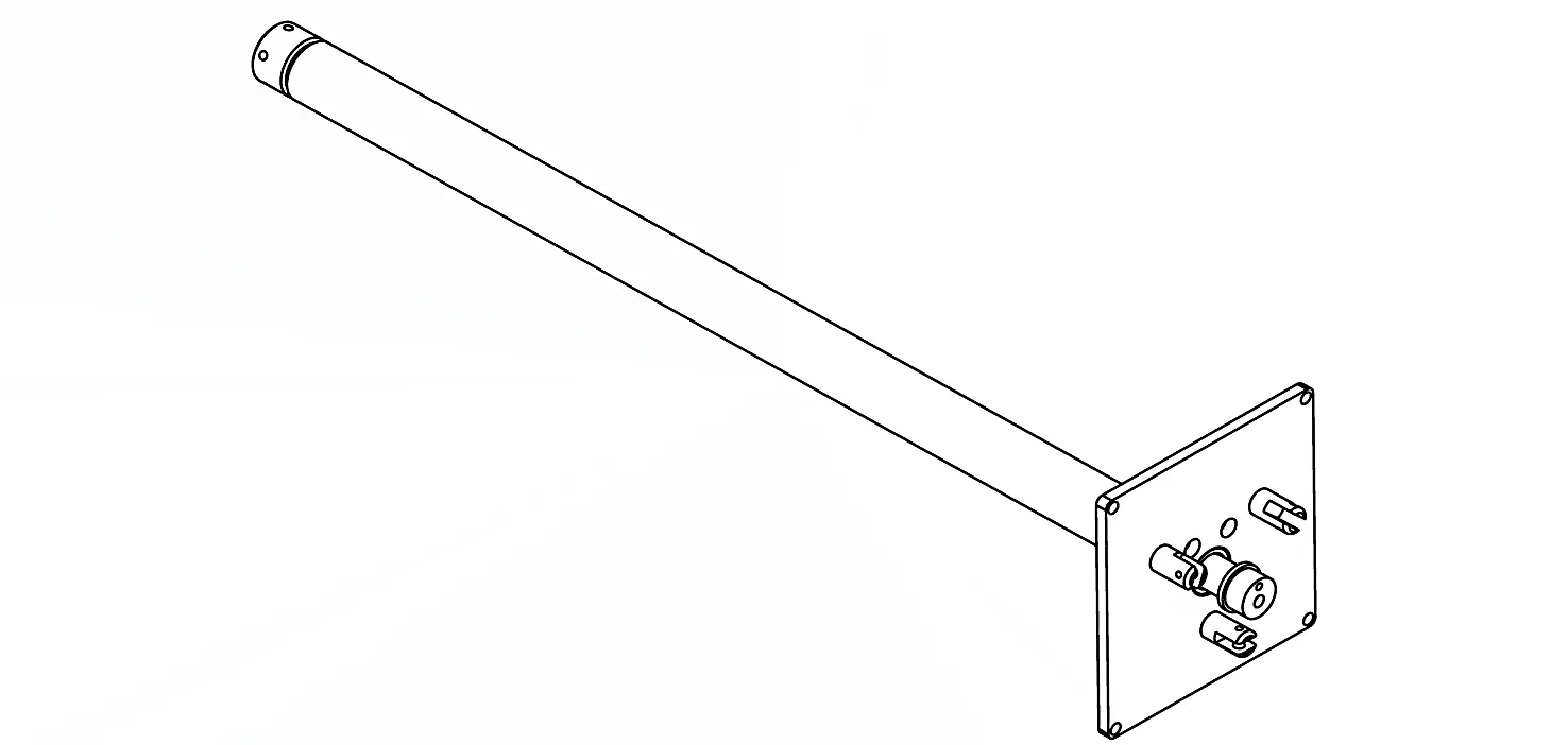
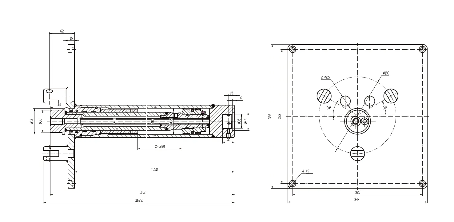
These are the largest cylinders on the machine. They require exceptional buckling strength due to their long stroke. The rods are typically manufactured from high-yield 4140 alloy steel, induction hardened, and utilize spherical bearing clevis mounts to allow for slight structural deflection without binding the seals.
Master-Slave Leveling Circuit
A brilliant application of fluid mechanics. As the main boom raises, it forces fluid out of a “master” cylinder at the boom base directly into a “slave” cylinder attached to the basket. Because the bore and stroke are mathematically matched, the basket remains perfectly level automatically, regardless of the boom angle.
Telescopic boom extension cylinders are often hidden entirely within the boom structure. These long, slender cylinders push the telescoping sections outward. Because they are enclosed, visual inspection is difficult, making seal reliability absolutely paramount. In highly advanced AWPs, extension cylinders utilize regenerative hydraulic circuits. By routing the exhaust fluid from the rod end directly back into the cap end (rather than back to the tank), the extension speed is significantly increased without requiring a larger, heavier hydraulic pump.
04. Absolute Safety: The Critical Role of Load Holding Valves
The most terrifying scenario for any MEWP operator is a ruptured hydraulic hose while elevated. Gravity immediately attempts to pull the boom or scissor stack down, forcing fluid out of the cylinder at catastrophic velocities. To prevent this, safety regulations mandate that all lifting and extending cylinders on AWPs be equipped with integral load-holding valves. The aerial work vehicle cylinders produced for this sector feature Counterbalance Valves (CBVs) or Pilot-Operated (PO) Check Valves directly flanged or cartridge-threaded into the cylinder head.
- 🛡️
Counterbalance Valves (CBVs)
CBVs serve a dual purpose: load holding and motion control. They prevent the cylinder from retracting until a pilot pressure is explicitly applied from the main control valve. Furthermore, if a heavy boom attempts to “run away” (lower faster than the pump is supplying fluid), the CBV restricts the exhaust flow, providing smooth, perfectly controlled deceleration. Typical pilot ratios in AWPs range from 3:1 to 4:1, ensuring stability without causing system shudder.
- 🌡️
Thermal Relief Integration
Hydraulic fluid expands when heated. If a boom lift is elevated in the morning chill and sits in the hot midday sun, the fluid locked inside the cylinder by the CBV expands. This thermal expansion can easily generate internal pressures exceeding 500 bar, which could permanently swell the cylinder barrel or blow the seals. High-quality AWP CBVs incorporate a thermal relief function, allowing a few drops of fluid to bleed off and normalize the pressure, protecting the structural integrity of the cylinder.
05. Advanced Tribology: Sealing Systems for Zero-Drift Operations
Tribology—the study of friction, wear, and lubrication—is the science that determines whether a lift cylinder will last 10,000 hours or fail in 100. For AWPs, operators demand micro-level positioning accuracy. If a worker is maneuvering a basket near high-voltage lines, the platform must respond instantly and smoothly to joystick inputs. Poor seal design leads to “stiction” (stick-slip phenomenon), where the cylinder jerks into motion rather than gliding. This creates hazardous platform bouncing.
To combat stiction, premium AWP cylinders utilize composite seal profiles. Instead of standard Nitrile (NBR) O-rings, the piston seals often feature a Polytetrafluoroethylene (PTFE, or Teflon) dynamic ring energized by an NBR or FKM rubber expander. PTFE possesses an extremely low coefficient of friction, completely eliminating stick-slip behavior even at microscopic velocities. Additionally, high-performance Polyurethane (PU) U-cups are used for rod seals due to their unparalleled abrasion resistance and ability to handle extreme pressure spikes without extruding into the clearance gaps.
Protecting these internal seals is the external wiper seal (or scraper). AWP machines often operate in harsh environments—demolition sites, concrete pouring, or dusty shipyards. The wiper seal is a rigid, sharp-lipped polyurethane ring that aggressively scrapes dried cement, ice, or abrasive dust off the chrome rod as it retracts, ensuring that these destructive contaminants never breach the hydraulic fluid.
06. Metallurgical Properties and Environmental Resilience
The structural integrity of a lift cylinder relies entirely on its metallurgy. AWPs utilize seamless steel tubes (typically grades matching St52, E355, or 27SiMn) for the cylinder barrel. 27SiMn is particularly favored in high-stress applications due to its excellent combination of high tensile strength, high yield point, and good weldability. The welding process for the trunnions and end caps must adhere to strict AWS D1.1 structural welding codes, often requiring ultrasonic non-destructive testing (NDT) to guarantee zero porosity or micro-cracking in the weld zones.
🧪 The Hard Chrome Imperative
Because AWPs are typically stored outdoors, the piston rods face constant exposure to rain, snow, and corrosive industrial atmospheres. The rods undergo a multi-stage electrochemical hard chrome plating process. The industry standard requires a minimum plating thickness of 20 to 30 micrometers.
Quality validation involves aggressive Neutral Salt Spray (NSS) testing. Premium AWP cylinder rods must endure a minimum of 96 hours (and often up to 500 hours for specialized units) in a concentrated saline fog chamber without showing a single pit of red rust, corresponding to an ISO 10289 rating of 9 or 10. This ensures the rod remains perfectly smooth, preventing abrasive rust from chewing through the rod seals and causing catastrophic leaks.
07. Predictive Maintenance and ISO Cleanliness Standards
Over 75% of all hydraulic cylinder failures can be traced directly to fluid contamination. In the precision environment of an AWP hydraulic system, microscopic particulate matter acts like liquid sandpaper. Maintenance protocols must strictly adhere to the ISO 4406 fluid cleanliness standard. For systems utilizing sensitive proportional directional valves and high-pressure lift cylinders, fluid cleanliness must be maintained at a minimum code of 18/16/13.
Diagnostic: Cylinder Sponginess
If the platform feels bouncy or “spongy” upon reaching the desired height, air has been entrained in the hydraulic system. Because air is highly compressible (unlike hydraulic oil), it acts as a mechanical spring. This must be resolved immediately by performing a systematic bleed of the cylinders, typically by fully extending and retracting the machine unloaded multiple times while slightly cracking the highest fitting to purge the trapped air.
Diagnostic: Fluid Discoloration
Hydraulic fluid should be clear and amber. If the fluid appears milky or cloudy, water ingress has occurred, likely due to a failing rod seal allowing rain water past, or heavy condensation in the reservoir. Water degrades the fluid’s lubricity and causes rapid oxidation of internal steel cylinder walls. The system must be flushed immediately.
08. Economic Lifecycle and Global Sourcing
For fleet rental companies managing hundreds of MEWPs, the Total Cost of Ownership (TCO) of hydraulic cylinders is a major economic metric. While resealing a leaking cylinder is standard practice, deep scoring on the barrel or a bent piston rod necessitates full unit replacement. When evaluating replacement economics, procurement managers must look beyond initial unit cost.
Proper market sourcing of aerial work vehicle hydraulic cylinders provides access to standardized, high-quality replacement units that meet or exceed OEM specifications. An intelligently sourced aftermarket cylinder featuring upgraded PU seals and thicker chrome plating can often outlast the original factory component, dramatically reducing machine downtime and improving fleet ROI.
Ensure Ultimate Safety and Reliability
Don’t compromise on the actuators that keep your personnel safe and your fleet operational. Explore our catalog of precision-engineered, rigorous-tested MEWP lift cylinders designed for the absolute harshest environments.














