
Hydro-Engineering Equipment Series · Monograph XXIII
Silinder Pengangkat Puncak Bendungan untuk Sistem Bendungan Hidraulik
Hydraulic elevator dams, spillway flap gates, and water conservation barrier structures play a critical role in urban flood control, ecological river restoration, and agricultural irrigation reservoir management. Operating submerged directly within natural riverbeds, their primary crest elevation actuators face continuous immersion in sediment-laden water, bio-fouling, and severe electrochemical corrosion. This comprehensive engineering guide examines the mechanics, metallurgy, and heavy-duty anti-corrosion barrier architecture of double-acting welded piston-type dam crest lift cylinders. We analyze crest flap gate kinematics, high-strength alloy steel metallurgy, the root causes of outer barrel severe pitting corrosion, electroless nickel-phosphorus plating (ENP), and multi-layer marine epoxy heavy protective coating systems engineered for 30+ year submerged service life.
Electroless Nickel Plating
Heavy Marine Epoxy Coating
Engineering Specifications Matrix for Hydraulic Dam Crest Lift Cylinders
The following engineering parameters define the structural, metallurgical, sealing, and anti-corrosion benchmarks required for double-acting welded dam crest lift cylinders deployed in hydraulic water-control infrastructure.
| Engineering Parameter | Hydraulic Dam System Specification Standard |
|---|---|
| Equipment Category & Application | Hydro-Engineering Structures / Hydraulic Elevator Dams, Spillway Flap Gates & Water Barriers |
| Subsystem Motion Profile | Dam Panel Elevation & Flood Release Descent / Double-Acting Controlled Linear Actuation |
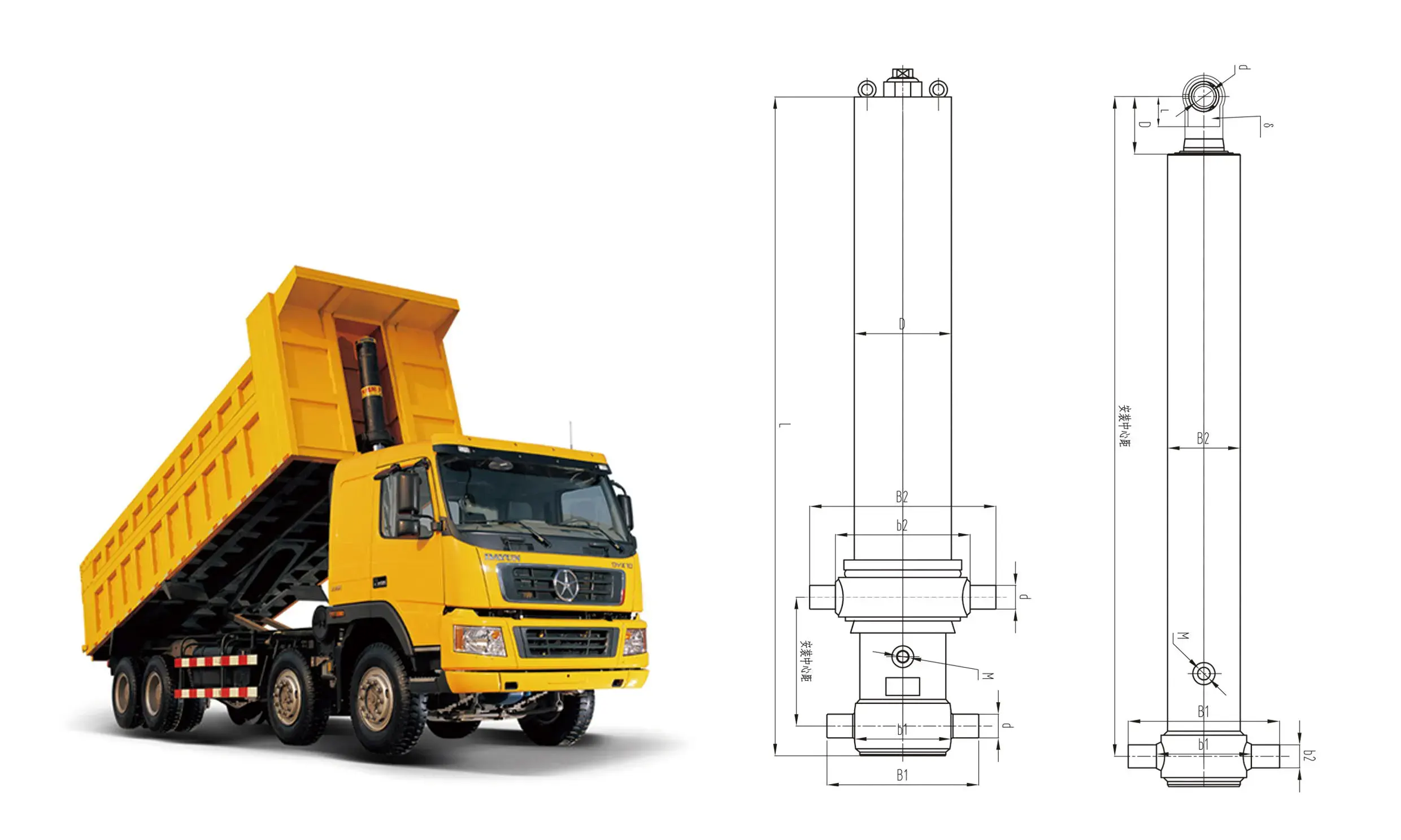
| Hydraulic Cylinder Name | Dam Crest Lift Cylinder (Heavy-Duty Submerged Piston Type) |
| Action Mode & Structural Type | Double-Acting Piston Cylinder (High-Thrust Extension Elevating / Controlled Powered Closing) |
| Manufacturing Construction | Robotic Full-Penetration Welded Heavy-Wall Tube Architecture (AWS D1.1 / ISO 15614) |
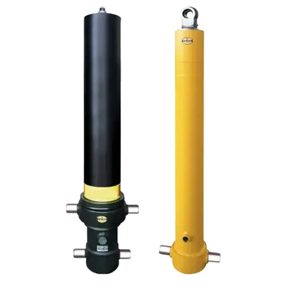
| Material System Metallurgy | High-Strength Seamless Alloy Steel (35CrMo / 42CrMo Quenched & Tempered Tubing) |
| Surface Finish & Plating | Electroless Nickel Plating (ENP) / Duplex High-Phosphorus Nickel-Chrome (30–50 μm) |
| Environmental Rating Class | Continuous Riverbed Immersion + Silt/Sand Abrasion + Bio-Fouling + Acidic Runoff |
| Working Conditions Profile | Lifting Heavy Reinforced Concrete/Steel Dam Gates (20 to 100+ Tons per Bay) |
| Primary Failure Mitigated | Outer Barrel Galvanic/Pitting Corrosion, Corrosion Fatigue Splitting, & Bio-Film Blistering |
| Recommended Engineering Keypoints | Heavy-Duty Marine Epoxy Coating System + ENP Rod Plating + FKM Fluorocarbon Seals |
| Nominal Operating Pressure | 16.0 MPa to 25.0 MPa (160 – 250 Bar) Continuous Working Relief Pressure |
Hydraulic Flap Gate Kinematics and Submerged Force Dynamics
Hydraulic elevator dams use articulated steel or concrete gate panels hinged along a reinforced riverbed foundation. During dry seasons or water storage periods, hydraulic cylinders extend to raise the dam panels into a vertical impoundment position, creating an elevated artificial lake. During heavy flood events, the cylinders retract, lowering the panels flush into riverbed recesses to allow unobstructed flood discharge and sediment flushing.
The raising and holding actions of each dam bay are driven by paired double-acting hydraulic lift cylinders pin-mounted between the riverbed embedded anchor structure and the back face of the dam panel. These large-bore actuators operate while partially or completely submerged in water for decades.
Hydrostatic Pressure Head and Breakaway Lifting Torque
The initial breakaway elevation of a submerged dam panel presents severe mechanical resistance. Upstream water depth creates a hydrostatic force (Fhydrostatic) acting perpendicular to the gate face:
Where ρwater is water density (1,000 kg/m³), g is gravitational acceleration (9.81 m/s²), Hwater is head water depth, and Wgate is bay width. In addition to hydrostatic head, riverbed silt, gravel, and sand deposit over the lowered gate panel, adding thousands of kilograms of deadweight soil overburden that must be overcome during initial cylinder extension.

Double-Acting Hydraulic Thrust Equations
Dam crest lift cylinders utilize a double-acting piston configuration to provide positive hydraulic force during both upward panel raising and powered downward closing against turbulent river currents:
Where Phyd is line pressure (16.0 to 25.0 MPa), Dbore is cylinder bore diameter (typically 160 mm to 320 mm for dam applications), and drod is the piston rod diameter (110 mm to 220 mm). Dual pilot-operated hydraulic check valves lock fluid inside the cap chamber, maintaining gate elevation indefinitely without hydraulic creep.
Root Cause Failure Analysis: Cylinder Barrel Severe Pitting Corrosion
Hydraulic dam cylinders operate in severe aquatic environments. River water contains dissolved oxygen, chloride ions, industrial effluent runoff, suspended sand abrasives, and biological organisms. Engineering surveys show that Cylinder Barrel Outer Wall Pitting Corrosion (缸筒腐蚀) Dan Crevice Corrosion Under Bio-Fouling Layer are the leading causes of structural degradation in submerged dam actuators.
When standard industrial cylinders coated with basic primer paints are installed in riverbed dam chambers, they experience rapid Electrochemical Corrosion within 24 to 36 months.
1. Electrochemical Pitting and Crevice Corrosion Mechanics
Natural river water acts as an electrolyte. On an unprotected carbon steel cylinder barrel, microscopic variations in material composition create localized galvanic micro-cells. Anodic oxidation dissolves iron atoms into solution:
As freshwater algae, freshwater mussels, and organic slime attach to the outer cylinder barrel, they form a dense, non-uniform bio-film cover. The steel beneath the bio-film becomes oxygen-depleted relative to adjacent open areas, creating a differential aeration cell. Dissolved chloride ions (Cl⁻) migrate into localized pits under the slime, forming acidic iron chloride (FeCl₂), which accelerates deep pitting corrosion into the pressure-retaining barrel wall.
2. Corrosion Fatigue Splitting Under Cyclic Pressure Loading
As deep corrosion pits form on the outer barrel surface, they act as sharp mechanical stress concentration notches. When the dam panel elevates or experiences turbulent river water vibration, high internal hydraulic working pressure (Phyd = 20.0 MPa) generates high circumferential hoop stress (σhoop) across the thinned barrel wall.
Combined cyclic hoop stress and localized pitting corrosion initiate corrosion fatigue cracks at the base of the pits. Over thousands of gate cycles, these cracks propagate inward through the barrel wall thickness, culminating in high-pressure fluid leaks and complete hydraulic failure.
1. Bio-Film Differential Aeration
Submerged algae and biological slime form oxygen-depleted zones on the outer tube wall, initiating severe localized crevice and pitting corrosion cells.
2. Acidic Pit Propagation
Chloride ions accumulate inside microscopic pits, lowering pH levels and rapidly eating away the steel barrel wall thickness beneath the painted surface.
3. Corrosion Fatigue Bursting
Deep corrosion notches concentrate hoop stress during high-pressure lifting cycles, propagating micro-cracks that split open the barrel wall.
Structural Metallurgy: Alloy Steel & Electroless Nickel Tribology
Hydraulic dam crest lift actuators require high yield strength to withstand heavy water pressure, wave impact shocks, and potential floating debris strikes. Standard structural carbon steels (such as Q235B or AISI 1020) offer low yield strength (~235 MPa), requiring excessive wall thickness that inflates cylinder weight.
Hydro-engineering lift cylinders deploy “High-Strength Seamless Alloy Steel” (such as “35CrMo” or “42CrMo”, conforming to GB/T 3077, equivalent to AISI 4140 / 42CrMo4 under EN 10083-3 standards) for both the heavy-wall barrel and solid piston rod.
Quenching and Tempering Thermal Processing Kinetics
Raw 35CrMo/42CrMo seamless tubes undergo complete Quenching and Tempering (Q&T). Material is heated to 850°C – 880°C for complete austenitization, polymer-quenched to produce fine martensite, and tempered at 580°C – 620°C to achieve a tempered martensite structure.
This heat treatment raises the yield strength (σS) to ≥ 850 MPa and ultimate tensile strength (σb) to ≥ 1000 MPa, with Charpy V-notch impact toughness exceeding 45 J at -20°C. High yield strength enables sleek, compact cylinder designs while providing an ultimate safety factor against dynamic water hammer surges.
| Steel Material Grade | Yield Strength (σS) | Tensile Strength (σb) | Charpy Impact Energy (-20°C) |
|---|---|---|---|
| Q235B (Standard Carbon Steel) | ≥ 235 MPa | 370 – 500 MPa | ≤ 20 J @ +20°C |
| Q345D (Low-Alloy Steel) | ≥ 345 MPa | 470 – 630 MPa | ≥ 34 J @ -20°C |
| 42CrMo High-Strength Alloy Steel (Q&T) | ≥ 850 MPa | ≥ 1000 MPa | ≥ 45 J @ -20°C |
Electroless Nickel Plating (ENP) / Duplex Coating System
Standard electroplated hard chrome contains microscopic crack networks that allow river water to seep through to the steel base under continuous immersion, causing under-film rust lifting. Dam lift cylinders deploy “Electroless Nickel Plating (ENP)” or a “Duplex High-Phosphorus Nickel-Chrome System” (20 μm high-phosphorus ENP underlayer + 25 μm hard chrome outer layer):
- ▸
Amorphous Zero-Porosity Nickel Barrier: Autocatalytic electroless nickel deposits a uniform, non-porous nickel-phosphorus alloy (10–14% P content) over the alloy steel rod, completely sealing the substrate against chemical and electrochemical attack. - ▸
High Scratch Resistance Outer Case: Induction hardening beneath the plating provides a 3.0 mm deep case (58–62 HRC), preventing rod indentations when river gravel strikes the extended rod. - ▸
Extreme Salt Spray & Immersion Endurance: Duplex ENP-Chrome coated rods pass 1,000-hour Neutral Salt Spray (NSS per ISO 9227) and acetic acid salt spray testing with zero corrosion pitting.
Recommended Configuration: Heavy Marine Epoxy Coating & Advanced Seals
Completely eliminating cylinder barrel pitting corrosion, bio-fouling degradation, and fluid leaks during 30+ years of submerged riverbed operation requires specifying an engineered “Heavy Duty Hydro-Engineering Protection Package” featuring three essential structural upgrades:
1. Multi-Layer Marine Epoxy Protective Coating System
The external surface of the outer alloy steel cylinder barrel undergoes Sa 2.5 near-white abrasive blast cleaning (ISO 8501-1), creating an anchor profile of 50–75 μm. The barrel is then coated with a 4-layer marine-grade barrier system total dry film thickness (DFT ≥ 450 μm):
- ▸
Inorganic Zinc-Rich Epoxy Primer (75 μm DFT): Provides active cathodic galvanic protection to the steel substrate if surface scratches occur. - ▸
High-Build Glass-Flake Epoxy Intermediate Coats (250 μm DFT): Microscopic glass flakes overlap horizontally within the epoxy matrix, creating a labyrinth barrier that blocks water molecules and chloride ion penetration. - ▸
Foul-Release / Anti-Fouling Fluoropolymer Topcoat (125 μm DFT): Provides a ultra-low surface energy finish that prevents algae, barnacles, and freshwater mussels from adhering to the cylinder body.
2. Water-Resistant Fluorocarbon (FKM) & Stainless Steel Accessories
All dynamic gland seals deploy high-modulus hydrolytically stable Fluorocarbon Elastomer (FKM / Viton) U-cups equipped with PEEK anti-extrusion back-up rings. External hydraulic fluid piping, port flanges, and air vent valves are manufactured exclusively from 316L austenitic stainless steel or duplex 2205 stainless steel, eliminating corrosion weak points.
3. Heavy Dual-Lip Brass-Cased Silt Scraper Ring
The outer gland mouth incorporates a heavy dual-lip scraper housed in a corrosion-proof naval brass casing. The outer scraper lip wipes away riverbed sand, silt sediment, and aquatic algae before the piston rod retracts into the primary seal chamber.
Specifying a robust welded hydraulic lift cylinder assembly engineered with alloy steel, heavy marine epoxy coating, and ENP rod plating guarantees 30+ year maintenance-free operation in hydraulic dam projects.
Preventive Maintenance, Fluid Hygiene, and Diagnostic SOP
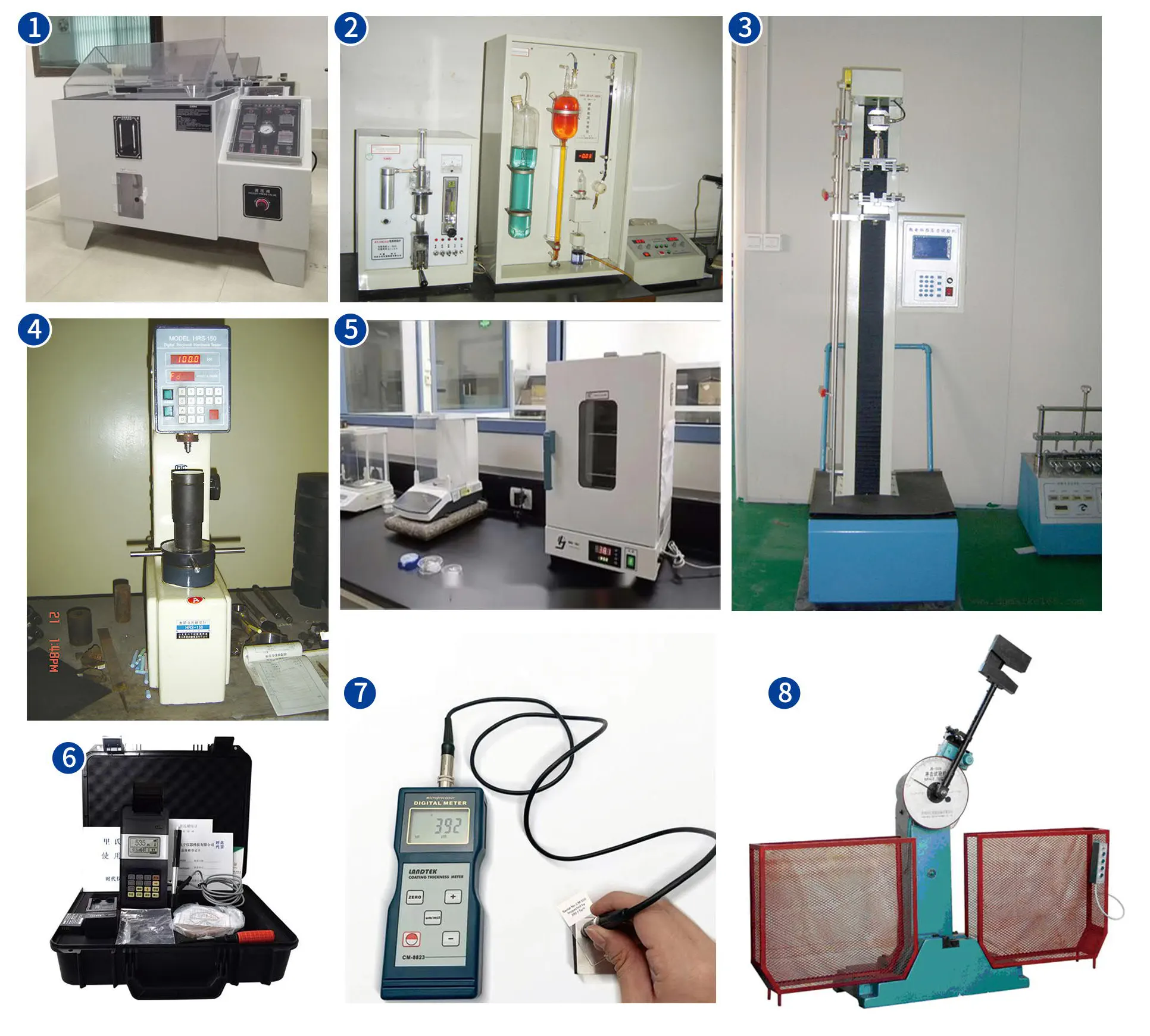
To maintain flood control safety and prevent environmental oil contamination in public waterways, hydro-engineering maintenance teams must execute strict periodic hydraulic inspection SOPs.
ISO Cleanliness Target and Biodegradable Oil Standard
Hydraulic fluid in dam gate systems should be maintained to an ISO 4406 cleanliness code of 16/14/11 or cleaner. Submerged dam cylinders should utilize non-toxic, synthetic ester-based biodegradable hydraulic fluids (HEES per ISO 15380) to protect river aquatic ecosystems in the event of minor seal leakage.
Step-by-Step Diagnostic SOP for Submerged Cylinders
Dam operators can perform underwater or dewatered inspection during annual flood-prevention maintenance windows using this diagnostic routine:
1. Ultrasonic Thickness & Coating Integrity Inspection
Dewater the cylinder pit or deploy divers with underwater ultrasonic thickness gauges (UT per ISO 16809). Measure barrel wall thickness at multiple locations around the tube circumference. Any wall loss exceeding 5% of nominal thickness indicates subsurface pitting corrosion requiring coating refurbishment.
2. Internal Piston Seal Pressure Holding Test
Raise the dam gate panel to maximum height, engage mechanical locking pins, and isolate the hydraulic power unit. Monitor cap chamber pressure gauges over a 24-hour dwell period. A pressure drop exceeding 0.5 MPa indicates internal piston seal bypass or pilot check valve seat wear.
Frequently Asked Questions: Dam Crest Lift Cylinder Engineering
What causes severe pitting corrosion on submerged hydraulic dam lift cylinders?
Severe pitting corrosion on submerged dam cylinders is caused by electrochemical micro-cells and bio-film differential aeration. When freshwater algae and organic slime attach to unprotected steel barrels, oxygen-depleted zones form beneath the bio-film. Dissolved river water chloride ions accumulate inside micro-cavities, creating acidic iron chloride that rapidly eats away the steel barrel wall thickness.
How does a multi-layer marine epoxy coating system protect submerged dam actuators?
A heavy-duty marine epoxy system (DFT ≥ 450 μm) combines an inorganic zinc-rich primer for galvanic cathodic protection, glass-flake intermediate coats that create an impermeable physical barrier against chloride ions, and a foul-release topcoat that prevents algae and bio-fouling attachment, ensuring 30+ year submerged protection.
Why is Electroless Nickel Plating (ENP) superior to standard chrome plating for dam cylinder rods?
Electroless nickel plating deposits an amorphous, non-porous nickel-phosphorus alloy coating over the steel substrate. Unlike micro-cracked hard chrome, the non-porous nickel barrier completely seals the underlying alloy steel against continuous river water immersion, eliminating under-film rust lifting and galvanic pitting corrosion.
Why are 35CrMo and 42CrMo alloy steels specified for hydraulic elevator dam cylinders?
35CrMo and 42CrMo high-strength alloy steels deliver yield strengths exceeding 850 MPa and Charpy V-notch impact energy absorption of ≥ 45 Joules at -20°C following quenching and tempering. High yield strength enables sleek cylinder designs that withstand dynamic water hammer surges and heavy sediment overburden without structural deformation.
Strategic Procurement and Total Cost of Ownership
For hydro-engineering authorities, municipal water boards, and dam construction contractors, unexpected cylinder failure on a flood-control barrier represents an unacceptable public safety hazard and results in costly underwater repairs. Sourcing low-cost commodity cylinders built with standard carbon steel or basic paint coatings leads to rapid pitting corrosion, water leaks, and elevated total cost of ownership (TCO).
Procurement engineering teams can evaluate technical options across hydro-engineering project hydraulic cylinder options to verify material impact certifications, ENP coating thickness, and marine epoxy specifications. Equipping hydraulic dam barriers with heavy-duty hydraulic lift cylinder category products engineered with 42CrMo alloy steel, multi-layer marine epoxy coatings, and ENP rod plating guarantees 30+ year submerged operational reliability across water conservation infrastructures.
Upgrade Your Dam Infrastructure with Corrosion-Proof Safety
Eliminate outer barrel pitting corrosion, prevent bio-fouling degradation, and ensure reliable floodgate control in submerged riverbed environments. Explore our complete series of double-acting, alloy steel dam crest lift cylinders engineered for hydraulic dam systems.














