
APPLICATION GUIDE · NO-TILLAGE MACHINERY · HYDRAULIC LIFT CYLINDERS
Vérins de levage pour
No-Tillage Machines
Complete Guide
Lift cylinders are the primary force transmission components in modern no-tillage machines — responsible for raising and lowering planting units, controlling seeding depth, and managing frame section position across multi-row conservation tillage equipment. This guide covers the complete engineering framework for main and auxiliary lift cylinders in no-tillage applications: spring return mechanisms, specification selection, hydraulic integration, field setup and maintenance practice.
Spring Return Mechanism
Conservation Tillage
LIFT CYLINDERS · APPLICATION ENGINEERING · JULY 2026
SYSTEM REFERENCE · NO-TILLAGE LIFT CYLINDER OPERATING PARAMETERS
BORE DIAMETER RANGE
50–90 mm
Standard bore sizes for no-tillage lift cylinder main and auxiliary applications
OPERATING PRESSURE
16–21 MPa
System operating pressure — tractor SCV supply to lift cylinder circuit
STROKE RANGE
145–400 mm
Stroke length determined by implement frame geometry and wheel clearance
SPRING RETURN FORCE
800–2 500 N
Built-in spring provides automatic retraction — replaces gravity or double-acting return
SECTION 01
Why No-Tillage Machines Require Specialised Lift Cylinders
No-tillage machines operate under conditions that are fundamentally different from conventional tillage equipment — and these differences impose specific engineering requirements on every lift cylinder in the hydraulic system. A conventional plough or disc harrow operates in pre-loosened or fallowed soil, where the implement frame encounters relatively uniform resistance and the cylinders function primarily as binary raise-lower actuators. A no-tillage machine, by contrast, must penetrate undisturbed, residue-covered soil at consistent seeding depth while managing variable ground contour, uncut stubble loads, and the accumulated weight of seed and fertiliser hoppers that changes throughout each field pass.
This operating environment creates three critical demands that standard agricultural cylinders cannot meet:
Precise depth control — consistent rod position under variable external load, ensuring uniform seed placement at the target depth across thousands of raise-lower cycles per season.
Rapid headland response — the implement must clear the ground within 2–3 seconds during headland turns, requiring fast extension speed and high-flow hydraulic port sizing.
Reliable spring return — automatic rod retraction to lower the implement without a dedicated return hydraulic line, simplifying the multi-cylinder circuits found on wide-format no-tillage machines.
The consequence of using a lift cylinder that is not engineered for no-tillage conditions manifests directly in seeding performance: inconsistent seed depth placement (the primary yield-limiting factor in no-till cropping systems), uneven implement frame height across multi-row machines (causing row-to-row depth variation), and premature seal failure from the higher cycle frequency that no-tillage machines impose — typically 200–400 raise-lower cycles per field day versus 20–40 for a conventional plough.
SECTION 02
Main vs Auxiliary Lift Cylinders — Functional Roles in No-Tillage Machines
Modern no-tillage machines use two distinct categories of lift cylinders — main and auxiliary — each serving a different functional role in the implement hydraulic system. Understanding the engineering distinction between these two cylinder types is essential for correct specification, because installing a main unit in an auxiliary position (or vice versa) creates a hydraulic system mismatch that degrades both implement control and cylinder service life.
Primary Frame Lift · High Force
◆
Raises and lowers the entire implement main frame — heaviest single load in the system
◆
Bore diameter: 70–90 mm — sized for main frame weight plus loaded hopper mass (1 500–4 000 kg)
◆
Master position in rephasing circuit — sets the reference height for all slave cylinders
◆
Spring return force: 1 500–2 500 N — must overcome loaded frame weight during lowering
Wing Section Lift · Contour Following
◇
Raises and lowers individual wing sections or row-unit groups — lighter loads, more frequent cycling
◇
Bore diameter: 50–70 mm — sized for wing section weight only (400–1 200 kg per section)
◇
Slave position in rephasing circuit — follows main cylinder to maintain implement frame level
◇
Spring return force: 800–1 500 N — wing sections are lighter but require faster contour response

Le spring return lift cylinders for no-tillage machines are engineered as a matched pair — main and auxiliary share the same mounting geometry and hydraulic port configuration but differ in bore diameter, spring return force, and stroke length to match their respective frame positions. Using matched cylinders from the same product family eliminates the hydraulic flow mismatch that occurs when lift cylinders from different manufacturers or product lines are combined in a single rephasing circuit — a common cause of uneven frame levelling on multi-section no-tillage machines.
SECTION 03
Spring Return Mechanism — Engineering Principles
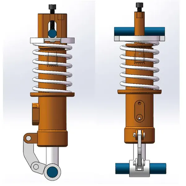
The spring return mechanism is the defining engineering feature that distinguishes no-tillage lift cylinders from standard agricultural hydraulic actuators. In a conventional double-acting cylinder, both the extension stroke (implement raise) and retraction stroke (implement lower) are powered by hydraulic pressure — requiring two hydraulic lines from the tractor SCV. A spring return lift cylinder replaces the hydraulic retraction with a built-in compression spring that stores energy during extension and releases it to retract the rod when pressure is released.
This engineering approach delivers three specific advantages in no-tillage applications:
Reduced hydraulic line complexity
It reduces the number of hydraulic lines from tractor to implement — a critical benefit on multi-section no-tillage machines where 4–8 lift cylinders may be required and available tractor SCV ports are limited. Each spring return cylinder eliminates one return hose, one tee fitting, and one potential leak point.
Consistent lowering rate
The spring return provides a constant-force retraction that is independent of tractor hydraulic flow rate variation — eliminating the implement “slamming” that occurs with gravity-return single-acting cylinders when the operator releases the SCV lever quickly.
Passive downpressure assist
The spring force provides a passive downpressure component during the initial lowering stroke — supplementing frame weight to ensure disc openers or coulters penetrate residue-covered soil before the full implement weight transfers to the ground contact tools.
SPRING RETURN ENGINEERING DATA · NO-TILLAGE LIFT CYLINDER OPERATING CHARACTERISTICS
| PARAMÈTRE | MAIN CYLINDER | AUXILIARY CYLINDER | ENGINEERING RATIONALE |
|---|---|---|---|
| Spring preload (rod extended) | 1 500–2 500 N | 800–1 500 N | Must overcome static friction + loaded frame weight at start of retraction |
| Spring force at full compression | 3 200–4 500 N | 1 800–2 800 N | Higher force at full compression — additional hydraulic pressure required to extend against spring |
| Retraction time (full stroke, unloaded) | 1.5–2.5 s | 1.0–2.0 s | Determined by spring force vs oil flow rate through exhaust port restriction |
| Spring cycle life (rated) | ≥ 500 000 | ≥ 500 000 | Chrome-silicon alloy spring wire — fatigue life exceeds seal replacement interval |
| Extension force penalty vs non-spring | +8–12% | +6–10% | Hydraulic pressure must overcome spring during extension — modest trade-off for return functionality |
The spring return mechanism introduces a deliberate engineering trade-off: the hydraulic system must supply approximately 8–12% more pressure during extension to compress the spring. This trade-off is accepted in no-tillage applications because the alternative — routing double-acting hydraulic lines to every lift cylinder position — adds complexity, weight, potential leak points, and consumes additional tractor SCV ports needed for other implement functions such as seed metering drive, marker arms, and fold cylinders on multi-section machines.
SECTION 04
Technical Specifications and Selection Parameters
Selecting the correct lift cylinder specification for a no-tillage machine requires matching four interdependent parameters: bore diameter (determines available lifting force at system pressure), stroke length (determined by implement frame geometry and ground clearance), rod diameter (determines buckling resistance under side-loading from uneven terrain), and spring return force (must overcome loaded implement weight at the start of retraction). An undersized bore produces insufficient force; an oversized bore wastes hydraulic flow and creates unnecessarily slow cycle times.
| NO-TILL MACHINE TYPE | MAIN BORE × STROKE | AUX BORE × STROKE | ROD DIA | APPLICATION TYPIQUE |
|---|---|---|---|---|
| 4-row no-till seeder (3-point) | Ø70 × 200 mm | Ø50 × 145 mm | Ø36 mm | Compact no-till seeder, 60–90 HP tractor, single frame section |
| 6-row precision no-till planter | Ø70 × 250 mm | Ø63 × 200 mm | Ø36 mm | Mid-size no-till, 90–130 HP, 3-section folding frame |
| 8–12 row no-till air seeder | Ø80 × 300 mm | Ø63 × 250 mm | Ø40 mm | Large no-till, 130–210 HP, 5-section folding frame, heavy seed/fertiliser load |
| 16+ row wide no-till drill | Ø90 × 400 mm | Ø70 × 300 mm | Ø45 mm | Wide-format no-till drill, 210+ HP, 7-section frame, pull-type configuration |
Selection note: Bore diameter determines force output at system pressure — a Ø70 mm bore lift cylinder produces approximately 6 160 kg of extension force at 16 MPa (F = P × A = 16 × π/4 × 70²). For a 4-row no-tillage seeder with 2 000 kg loaded frame weight and two main lift cylinders, each cylinder must produce at least 1 000 kg — a Ø70 bore at 16 MPa provides more than adequate margin. The full vérin de levage range covers bore diameters from 50 mm to 180 mm for applications from compact no-tillage seeders to heavy-duty aerial work platforms and mobile machinery hydraulic cylinders.
SECTION 05
Hydraulic Integration and Field Installation
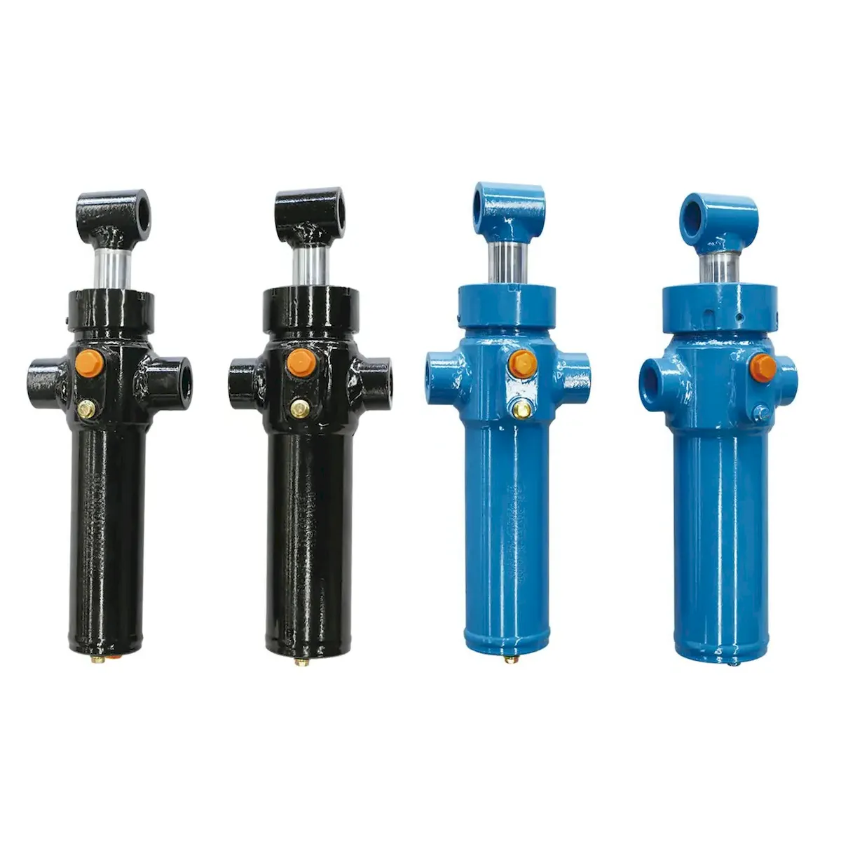
Hydraulic integration of lift cylinders into a no-tillage machine involves three system-level considerations that determine whether the cylinders perform to specification in the field:
REPHASING CIRCUIT CONFIGURATION
Series rephasing (used on most 3-section and 5-section no-tillage machines) connects the rod-end port of the master lift cylinder to the cap-end port of the first slave, so that oil displaced from the master during extension flows directly into the slave, forcing both to extend at proportional rates regardless of load difference between main frame and wing sections.
FLOW RATE MATCHING
The tractor SCV must supply sufficient flow to extend all cylinders within the operator’s expected raise time (typically 3–5 seconds). A cylinder with an 80 mm bore and 300 mm stroke displaces approximately 1.5 litres per stroke; a 5-section machine with six lift cylinders displaces approximately 9 litres total, requiring an SCV output of at least 27 l/min to achieve a 3-second full raise. Tractors below 20 l/min SCV output should be matched with smaller-bore lift cylinders to avoid unacceptably slow raise times.
EXHAUST FLOW RESTRICTION
When the operator releases the SCV to lower the implement, oil in the cap-end chamber must flow back to the tractor reservoir. If the return line is unrestricted, the spring return force drives the implement down at an uncontrolled rate — creating ground impact that damages disc openers and compresses seed furrows. A properly configured installation includes a flow control valve (or needle valve) in the return line to limit lowering to 2–3 seconds full stroke, producing a controlled, cushioned descent without ground impact shock.
SECTION 06
Maintenance, Inspection and Troubleshooting
Lift cylinders in no-tillage machines operate in one of the most demanding seal environments in agricultural hydraulics — high cycle frequency (200–400 cycles per day), exposure to soil dust and crop residue, and intermittent side-loading from uneven terrain. A structured maintenance programme extends service life from the typical 2–3 seasons (without maintenance) to 5–7 seasons before seal replacement is required.
Daily — Pre-Operation Visual Inspection
✓
Inspect rod surface for scoring, pitting, or chrome damage — any visible defect accelerates seal wear exponentially
✓
Check for external oil weepage at rod seal area — early warning before full leak develops
✓
Verify mounting pin retention clips are secure — missing clips allow pin migration that damages eye bushings
✓
Clear accumulated crop residue and soil debris from around the rod seal and wiper — debris ingestion is the primary seal failure cause
Seasonal — End-of-Season Service (Before Storage)
⚙
Retract all cylinder rods fully — minimises exposed rod surface area and reduces corrosion risk during off-season storage
⚙
Apply corrosion-preventive oil film to any exposed rod surface — critical for storage periods exceeding 3 months
⚙
Grease all mounting pin bushings — packed grease prevents moisture ingress and bushing corrosion
⚙
Rephase the entire hydraulic circuit — ensures all lift cylinders start the next season at synchronised positions
Troubleshoot — Common Field Problems and Root Causes
Implement lowers slowly or incompletely
→ Spring fatigue (loss of return force) or restricted return line — check spring free length vs specification; clean or replace flow control valve
Uneven frame height (one wing low)
→ Rephasing circuit out of sync — fully extend all lift cylinders to rephase; check for internal bypass leakage in the low-side cylinder
Cylinder creep (implement sinks when raised)
→ Internal piston seal failure — oil bypasses from cap-end to rod-end; lift cylinder requires seal kit replacement
External rod seal leak
→ Rod surface damage from debris ingestion has destroyed seal lip — rod requires re-chroming or cylinder replacement
FAQ sur l'application
No-Tillage Lift Cylinder Engineering Questions
Can a standard double-acting hydraulic cylinder replace a spring return lift cylinder on a no-tillage machine?
A standard double-acting cylinder can physically replace a spring return unit if the mounting dimensions match — but this substitution creates a functional problem in most no-tillage hydraulic systems. The spring return lift cylinder works with a single-acting SCV circuit: hydraulic pressure extends the rod (raises the implement) and the internal spring retracts it (lowers the implement) when pressure is released. Substituting a double-acting cylinder requires routing a second hydraulic line to the rod-end port and connecting it to a double-acting SCV valve — consuming an additional SCV port and adding hose routing complexity. On machines with 4–8 lift cylinders, this may exceed the tractor’s available SCV capacity. Additionally, the lowering rate with a double-acting unit is controlled by SCV flow, which varies with engine RPM and lever position — producing less consistent lowering behaviour than the spring return mechanism.
How often should the internal spring in a no-tillage lift cylinder be replaced?
Under normal conditions, the internal compression spring should last 500 000 cycles or more — approximately 5–8 planting seasons at 300 cycles per day, 60 operating days per season. The spring is manufactured from chrome-silicon alloy wire (ASTM A401 or equivalent) with shot-peened surface finish for fatigue crack resistance. The practical replacement indicator is performance-based, not time-based: when lowering time increases noticeably (more than 50% longer than original) or the implement does not reach full working depth under spring force alone, the spring has lost sufficient preload to warrant replacement. Spring replacement is typically combined with a seal kit service, since the cylinder must be fully disassembled to access the spring — combining both in a single service eliminates double labour cost.
What is the difference between spring return and standard lift cylinders for no-tillage machines?
Spring return lift cylinders include an internal compression spring that provides automatic rod retraction when hydraulic pressure is released — designed for single-acting circuits where the tractor SCV provides pressure only for extension (raise). Standard (non-spring) lift cylinders are double-acting units requiring hydraulic pressure for both extension and retraction — used where the tractor provides a double-acting SCV valve with sufficient port capacity. The spring version is more commonly specified on pull-type no-tillage machines where hydraulic hose routing between tractor and implement is a constraint; the double-acting version suits mounted or semi-mounted machines with short, direct hose runs and available double-acting SCV ports.
How do I rephase the lift cylinders on a multi-section no-tillage machine?
Rephasing synchronises rod positions across all cylinders in a series circuit so the implement frame is level. Follow these steps:
1.
Start the tractor engine and set RPM to rated speed for maximum hydraulic flow.
2.
Fully extend all cylinders — hold the SCV in raise position for 5–10 seconds after reaching full height to force all units to their mechanical stop.
3.
Fully retract all cylinders — spring return units retract automatically; double-acting units require SCV activation to lower.
4.
Repeat the full extend–retract cycle 2–3 times to purge trapped air and ensure all cylinders reach both mechanical stops.
5.
Lower to working height and verify frame level across all sections. On 5-section and 7-section machines, daily rephasing may be needed during intensive planting.
What seal material should be specified for lift cylinders operating in high-residue no-till conditions?
For high-residue no-tillage conditions where the cylinder rod is exposed to abrasive soil particles, crop stubble, and moisture, the recommended seal configuration is:
◉
Rod seal: Polyurethane (PU, 92–95 Shore A) — abrasion resistant, low-friction rod sealing
◉
Wiper seal: Polyester-reinforced PU or PTFE-filled NBR — effective debris exclusion
◉
Joint de piston : NBR or filled PTFE — internal sealing with mineral oil compatibility
◉
Static seals: NBR 70 Shore A O-rings — port connections and gland sealing
Avoid FKM/Viton rod seals in no-tillage applications — while FKM has superior chemical and temperature resistance, its higher hardness (75–85 Shore A) makes it less conformable to minor rod imperfections and less effective at excluding fine soil particles compared to softer polyurethane.
NO-TILLAGE LIFT CYLINDER APPLICATION SUPPORT
Selecting Lift Cylinders for Your No-Tillage Machine Project?
Our application engineering team provides specification support for main and auxiliary lift cylinders across all no-tillage machine configurations — from compact 4-row seeders to wide-format 16+ row air drills. Contact us with your implement frame weight, tractor SCV specification, and required stroke length for a matched cylinder recommendation.
Éditeur : Cxm














