
DEEP DIVE GUIDE · FORKLIFT SYSTEMS · HYDRAULIC LIFT CYLINDERS
Forklift Lift Cylinders
Deep Dive
Mast · Free-Lift · Tilt · Service
The forklift mast hydraulic system contains three distinct lift cylinder types — free-lift, main lift, and tilt — each operating under different load profiles, cycle frequencies, and clearance requirements. A counterbalance forklift in a busy distribution centre may complete 1 500–2 000 lift cycles daily, making the mast lift cylinder the highest-cycle hydraulic cylinder in most industrial facilities. This guide covers the full forklift lift cylinder system. This guide covers every cylinder position, mast configuration, seal selection, synchronisation, and the service regime that extends cylinder life in high-intensity operation.
Main Lift Mast
Tilt Cylinder
LIFT CYLINDERS · FORKLIFT APPLICATION ENGINEERING · JULY 2026
REFERENCE · FORKLIFT MAST CYLINDER PARAMETERS BY TRUCK CLASS
FRÉQUENCE DU CYCLE
500–2 000/day
Highest of any industrial hydraulic cylinder — seal material selection critical
FREE-LIFT BORE
50–90 mm
Plunger-type, single-acting — raises fork carriage within inner mast section
MAIN LIFT BORE
40–100 mm
Two cylinders per mast — synchronised via rephasing ports for uniform extension
PRESSION DU SYSTÈME
18–25 MPa
Tilt cylinders at upper range during forward tilt under full rated load
SECTION 01
Forklift Mast Types and Cylinder Configuration
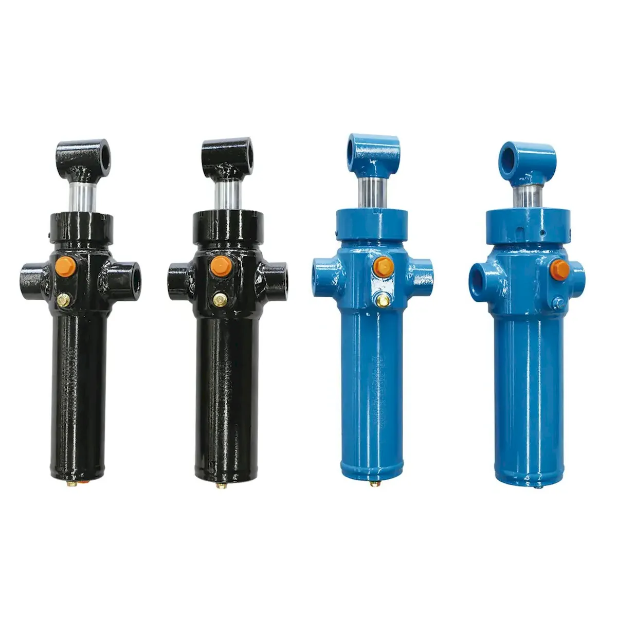
Forklift mast configurations determine which cylinder positions are present and how they interact. The three most common mast types each use a distinct cylinder arrangement:
SIMPLEX
MAST
Two main lift cylinders only — no free-lift cylinder. The forks begin rising immediately as the main cylinders extend. Used on outdoor rough-terrain forklifts and heavy-capacity machines where indoor clear height is not a constraint. Simple circuit, lowest cylinder count, easiest to service. Bore: 60–150 mm, stroke: 1 200–3 000 mm depending on lift height.
DUPLEX
MAST
One free-lift plunger + two main lift cylinders — the standard configuration for indoor warehouse forklifts. The free-lift plunger raises the fork carriage within the inner mast section first (no mast extension, no height increase), allowing loads to be lifted within the building’s clear height before the outer mast section begins extending. This is the most common forklift mast configuration globally — the vast majority of counterbalance and reach truck lift cylinders follow this layout.
TRIPLEX
MAST
One free-lift plunger + two main lift cylinders + two secondary extension cylinders — used for high-lift applications (6–10 m) in high-bay warehouses. The three stages of extension allow maximum lift height from a compact collapsed mast height, enabling the forklift to enter a low-clearance building entrance but place loads at high rack levels. The most complex hydraulic circuit — synchronisation across three stages requires precision rephasing ports in each stage of the lift cylinder.
SECTION 02
Free-Lift Plunger Cylinder — Function and Specification
The free-lift plunger cylinder is the simplest of the three mast cylinder types — a single-acting hydraulic plunger that extends under oil pressure and retracts under gravity and the weight of the fork carriage. It has no conventional piston seal — only a plunger seal at the gland and a wiper to exclude contamination. Despite its simplicity, the free-lift cylinder is the most contamination-sensitive component in the mast because it lacks the enclosed oil bath that lubricates a piston-type cylinder’s internal surfaces.
PLUNGER DIAMETER
50–90 mm, depending on fork carriage weight and the rated capacity of the truck. The plunger must support the dead weight of the carriage plus rated payload during the free-lift phase.
ACCIDENT VASCULAIRE CÉRÉBRAL
Equal to the free-lift height — the distance the fork carriage can travel within the inner mast before the outer mast begins to extend. Typically 400–800 mm for standard duplex masts.
CRITICAL WEAKNESS
The plunger seal and wiper are the only contamination barriers. Contaminated hydraulic oil circulates directly across the plunger surface 1 500+ times daily in a busy truck — ISO class 15/13/10 or better is mandatory. Dirty oil on the free-lift plunger destroys the gland seal within weeks.
SECTION 03
Main Lift Cylinders — Synchronisation and Rephasing
The two main lift cylinders in the mast run in parallel on the mast structure — one on each side of the outer mast rail. They must extend and retract synchronously; if one cylinder extends faster than the other due to internal bypass leakage differences, the mast tilts laterally and the fork carriage binds against the mast guides. Rephasing ports in the lift cylinder barrel prevent cumulative synchronisation error from developing across multiple cycles.
HOW REPHASING PORTS WORK
ÉTAPE 1
During normal operation, both main lift cylinders receive equal oil flow and extend at the same rate. Minor differences in seal friction cause small synchronisation errors to accumulate gradually across many cycles.
ÉTAPE 2
At full extension, the faster cylinder’s piston uncovers a small bypass port drilled through the cylinder wall just before the end stop. This connects the cap-end chamber to the rod-end, allowing the faster cylinder to halt and the slower one to catch up.
ÉTAPE 3
Once both cylinders reach the rephasing position (recognisable by a brief jerk or hesitation at full extension), synchronisation error is reset to zero and the next cycle begins from a perfectly equal starting position. Rephasing should occur on every full-extension cycle.
A mast that tilts laterally during lifting and does not rephase correctly at full extension indicates that one cylinder’s internal piston seal bypass rate has exceeded the rephasing port’s correction capacity — typically when bypass leakage exceeds 3–5 ml per minute at rated pressure. At this point, seal replacement is required to restore synchronisation within the design tolerance of ±5 mm across the full mast stroke.
SECTION 04
Tilt Cylinders — High-Pressure Double-Acting Operation
The tilt cylinders are the highest-pressure components in the forklift hydraulic mast system. Their function is to tilt the entire mast assembly forward (typically 5–6°) for load placement and rearward (typically 12°) for load carrying. Forward tilt of a fully loaded mast shifts the load’s centre of gravity toward the front axle, increasing the effective load on the tilt cylinders dramatically compared to the fork dead-weight alone.
| TRUCK CAPACITY | TILT CYL. BORE | ACCIDENT VASCULAIRE CÉRÉBRAL | FWD TILT PRESSURE | SPECIAL REQUIREMENT |
|---|---|---|---|---|
| 1–2 t counterbalance | 40–55 mm | 150–250 mm | 16–20 MPa | Clevis both ends, ±angular freedom |
| 2–3.5 t counterbalance | 50–70 mm | 200–320 mm | 18–24 MPa | PU rod seals, synchronised pair |
| 4–7 t heavy counterbalance | 63–90 mm | 280–450 mm | 20–28 MPa | High-pressure PU seals, FKM option for hot environments |
| Reach truck / VNA | 40–60 mm | 100–200 mm | 16–20 MPa | Short stroke, high cycle, compact envelope |
SECTION 05
Seal Selection for High-Cycle Forklift Applications

The forklift mast lift cylinder system operates under conditions that eliminate NBR as a viable rod seal material at any serious duty level. The combination of high cycle frequency, oil contamination from an environment where the fork is constantly near the floor, and temperature cycling from cold start to sustained operating temperature creates a degradation environment that NBR seals typically survive for 6–12 months before showing leakage. Polyurethane (PU) is the correct standard for all three mast cylinder rod seal positions:
FREE-LIFT
PISTON
PU 90–95 Shore A plunger seal + metal scraper wiper. The plunger seal must tolerate the full range of contamination from the floor environment — the free-lift plunger extends from the mast base, which is always within 100 mm of the warehouse floor and its ingested dust. Metal scraper is mandatory; polymer-only wipers allow fine silica particles to reach the seal and destroy it within a few thousand cycles. ISO cleanliness class 15/13/10 minimum for the hydraulic oil circuit supplying the free-lift.
MAIN LIFT
CYLINDERS
PU 88–92 Shore A rod seal + PU wiper + PTFE-backed NBR piston seal. The main lift cylinders are less contamination-exposed than the plunger but cycle at the same frequency. The PTFE-backed piston seal provides the low internal bypass necessary for correct rephasing — a high-bypass piston seal prevents the rephasing port from resetting synchronisation correctly and results in progressive lateral tilt development.
TILT
CYLINDERS
PU 92–95 Shore A rod seal + PU wiper + FKM option for hot environments. The tilt cylinders operate at the highest pressure of the three mast positions. High-Shore-A polyurethane resists the extrusion damage that lower-hardness seals experience at 20–25 MPa. For trucks operating in hot-climate facilities (above 40°C ambient), FKM rod seals are preferred over PU because the tilt cylinder temperature rises faster than the main lift cylinders due to the sustained pressure holding during loaded tilt.
Seal kits for the full range of forklift mast vérins de levage — free-lift plunger, main lift, and tilt cylinder positions — are available in both standard NBR (for light-duty applications) and polyurethane upgrade kits (for high-cycle industrial service). The vérin de levage product range covers all standard bore sizes across the major forklift truck weight classes.
SECTION 06
Forklift Mast Cylinder Service Schedule
At 1 500 cycles per day and 250 working days per year, a distribution-centre forklift accumulates 375 000 mast lift cylinder cycles annually. This is equivalent to the full design life of many industrial cylinders — achieved in a single year. The service schedule below reflects this intensity.
Daily
Start of shift
Check hydraulic oil level. Inspect all visible rod surfaces — free-lift plunger, main lift rods, tilt rods — for oil weeping or contamination accumulation. Verify the mast rises and lowers smoothly with no lateral drift or binding. Check that rephasing occurs cleanly at full extension (recognisable as a brief hesitation before lowering begins).
250 hours
~6 weeks intensive
Replace hydraulic oil filter element. Take oil sample for ISO cleanliness analysis — do not wait for filter bypass indicator. Check all mast roller bearings for lateral play; re-grease mast rail contact points. Inspect tilt cylinder clevis pins for wear.
500 hours
~3 months intensive
Change hydraulic oil if analysis shows ISO class above 16/14/11 or water above 0.1%. Measure lateral mast tilt with both cylinders at 50% extension and rated load — tilt exceeding 3 mm indicates synchronisation failure requiring seal rebuild. Full mast rail lubrication.
Annual
375 000 cycles
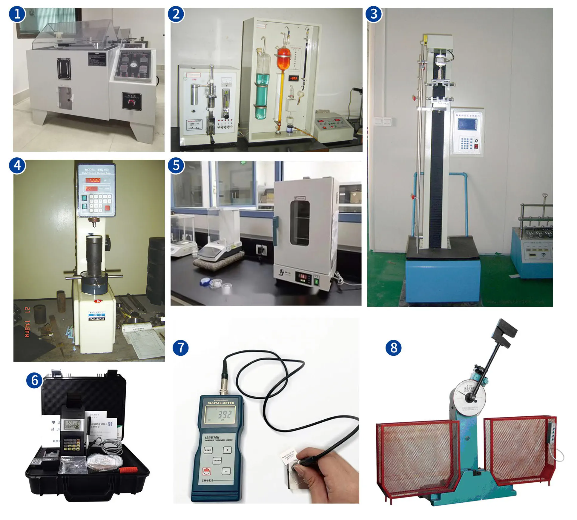
Full seal kit replacement on all three cylinder positions — free-lift, main lift, and tilt — as a preventive measure regardless of visible leakage. Measure plunger rod chrome thickness (eddy-current gauge) — below 15 μm triggers re-plating. Inspect rephasing port orifices for blockage with a fine wire probe. For industrial engineering and heavy-capacity forklift cylinder configurations, the vérin hydraulique pour génie industriel range provides additional bore and pressure options.
FAQ sur l'application
Forklift Lift Cylinder Questions
Q 01
My forklift mast tilts to one side when lifting — which cylinder is responsible?
Lateral mast tilt during lifting is caused by unequal extension rates in the two main lift cylinders of the mast system — the side that tilts down has the cylinder extending faster (less internal bypass leakage, receiving more flow). The lift cylinder on the high side is typically the worn one with higher internal bypass — it receives the same flow but cannot build equal pressure, so it lags behind. The diagnostic test is to isolate each cylinder from the circuit separately, apply rated pressure, close the supply valve, and measure pressure decay over 5 minutes. The cylinder with faster pressure decay has the higher bypass and needs its piston seal replaced. Replace seals in both cylinders simultaneously to prevent the repaired cylinder from compensating for the other’s remaining wear.
Q 02
What is the correct oil change interval for a forklift operating two 8-hour shifts per day?
A forklift operating two shifts per day with its lift cylinders accumulates approximately 4 000 operating hours per year — double the single-shift rate that most manufacturer service intervals are based on. At this duty level, the hydraulic oil should be changed every 500–750 hours (approximately every 6–9 weeks) rather than the 1 000–2 000 hour interval recommended for single-shift operation. Oil analysis is the most cost-effective way to calibrate the interval precisely: sample every 250 hours and plot the ISO cleanliness class trend. If class reaches 16/14/11 before 500 hours, shorten the interval; if it is consistently 15/13/10 at 750 hours, the interval may be extended to 1 000 hours for that specific machine and its operating environment.
Q 03
Why does my forklift lower slowly when the forks are loaded but quickly when empty?
This symptom — slow lowering under load, normal speed when empty — is the opposite of the typical internal bypass pattern and points specifically to a restriction in the lowering flow path rather than a cylinder fault. Single-acting cylinders lower under gravity; the lowering speed is controlled by the flow control valve (lowering valve or spool valve return orifice) that allows oil to leave the cylinder. When a load is present, the higher pressure in the cylinder forces more oil through any restriction, so a restriction that permits adequate no-load flow becomes the bottleneck under load. Check for a partially closed or sticky lowering control valve, a clogged return line filter, or a collapsed return hose. The lift cylinders themselves are rarely the cause of slow lowering — that symptom is almost always in the circuit, not the cylinder.
Q 04
Can I fit a longer-stroke main lift cylinder to increase the forklift’s lift height?
Not without a complete mast engineering review. The main lift cylinder stroke defines the maximum height to which the outer mast section can extend to which the outer mast section can extend — increasing stroke requires a longer mast rail, revised mounting brackets, and re-calculation of the mast’s structural stability and tip-over stability at the increased height. The forklift’s stability triangle and rated capacity are calculated for the original mast and cylinder specification; fitting longer lift cylinders changes the machine’s load chart and may invalidate the original type approval certification. If additional lift height is genuinely required, the correct approach is to contact the forklift manufacturer about mast upgrade packages that are type-approved for the machine, rather than modifying the mast cylinder independently. For applications requiring a custom mast cylinder specification, our technical team can provide a dimensioned lift cylinder quotation with the correct bore, stroke, and port configuration — contact us with the machine make, model, and target lift height.
FORKLIFT CYLINDER SPECIFICATION SUPPORT
Sourcing Forklift Mast Lift Cylinders?
Our application team matches free-lift plunger cylinders, main lift cylinders, and tilt cylinders to your forklift model and mast configuration — supplying the correct bore, stroke, port positions, and high-cycle polyurethane seal kit in a single order.
Éditeur : Cxm














